
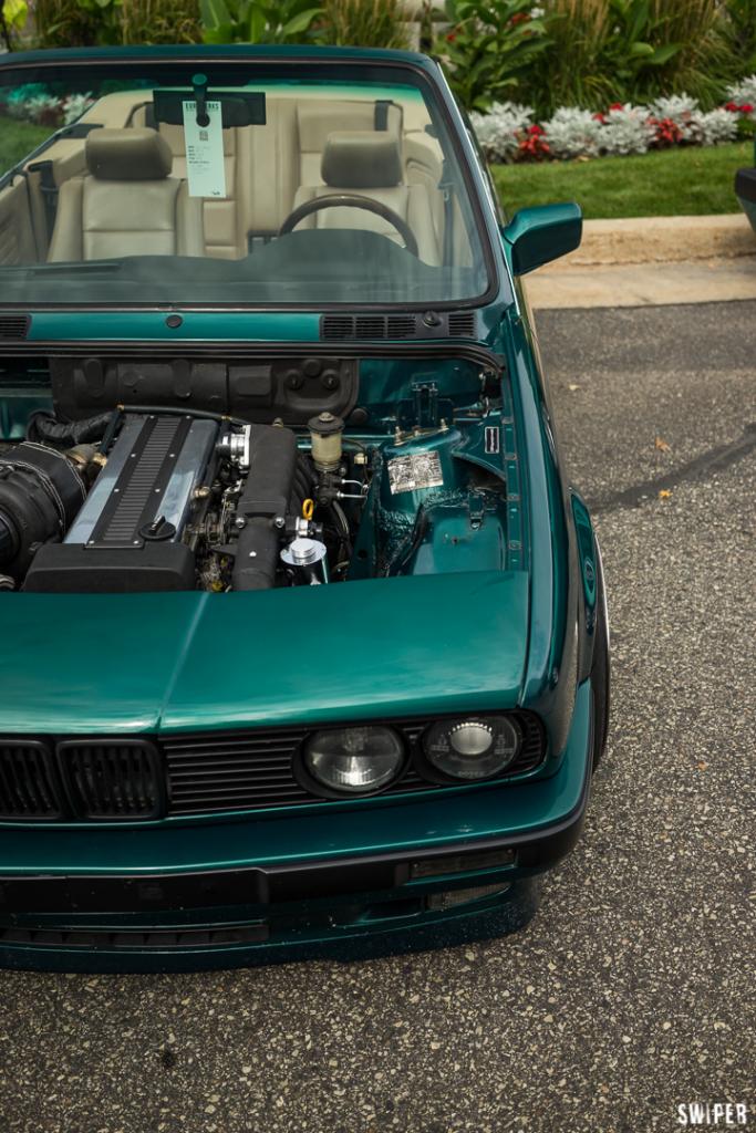
540i Swapped Rat rod Build thread
-
very cool!
seconded. it appears there is room for the coilover where you've placed that yellow connecting rod. are you using an undersized spring/shock and but increasing its effectiveness with the pivot arm?
what is the connecting rod coming forward from the pivot arm?
There is a couple reasons why i have the coil-over mounted horizontally .
1. Keep it Clear of road Hazards like Dirt, rocks, Ect.
2. I am using a under rated spring. So with the Cantilever allows me to achieve my desired spring rate with some sacrifice of overall suspension Travel. Because i honestly don't know what the project will weigh in at. I may have to re-fabricate the Cantilever Section. But This may be to stiff.
-
Yeah this project was always intriguing, but has certainly caught more of my interest seeing things being modeled!
The shear area on that upper shock mount seems reasonable if you've got good penetration welds on both plates.
I think I saw the knuckles in a picture on a previous page, but are those a standard purchased component?
I've always thought it would be cool to do a ground up build like this, so I really look forward to the continuation of this!
-
Nice work! Solidworks?
I have so many questions.(Sorry) Is there a reason you are going with a cantilever set up? How did you calculate the the pivot arm length? Are there any shear concerns with the shock mounted on the top of the tube like that without any linear support? You obviously peaked my interest. I like what I see and I am very glad this isn't a dead thread.
Yes the Cad software i use is Solid-works.
There is a couple reasons why I'm using a cantilever.
1. I have the coil-over mounted horizontally To Keep it Clear of road Hazards like Dirt, rocks, Ect.
2. I am using a under rated spring. So with the Cantilever allows me to achieve my desired spring rate with some sacrifice of overall suspension Travel. Because i honestly don't know what the project will weigh in at. I may have to re-fabricate the Cantilever Section. But This may be to stiff.
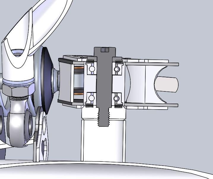
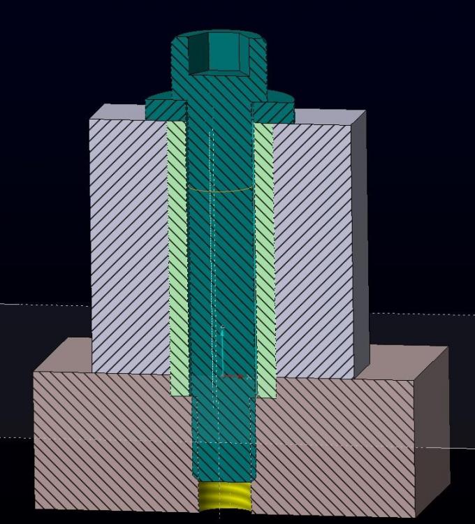
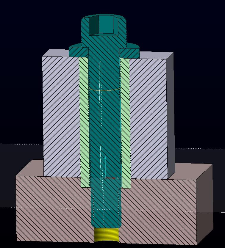
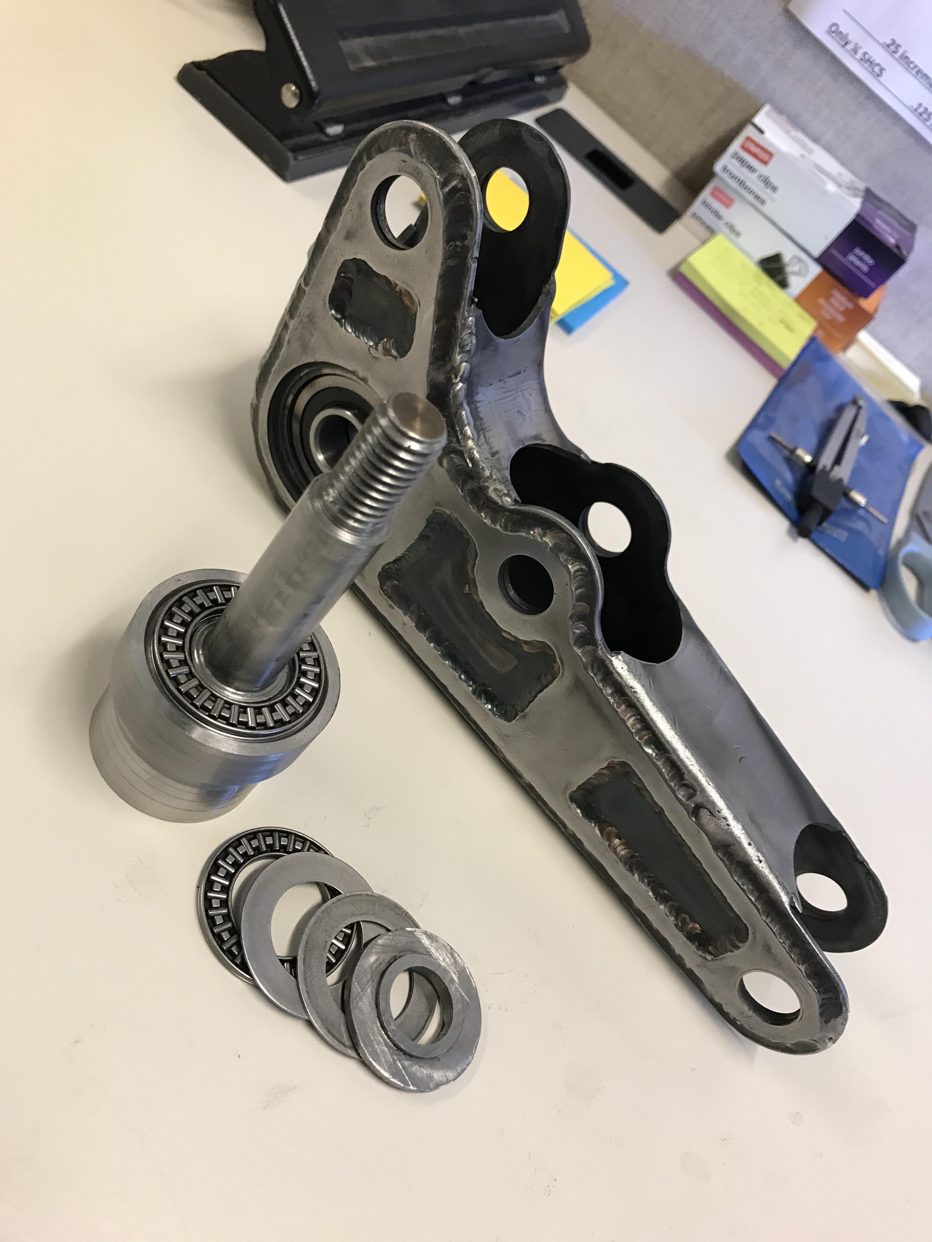
Attached is a image of a section View of the Cantilever.
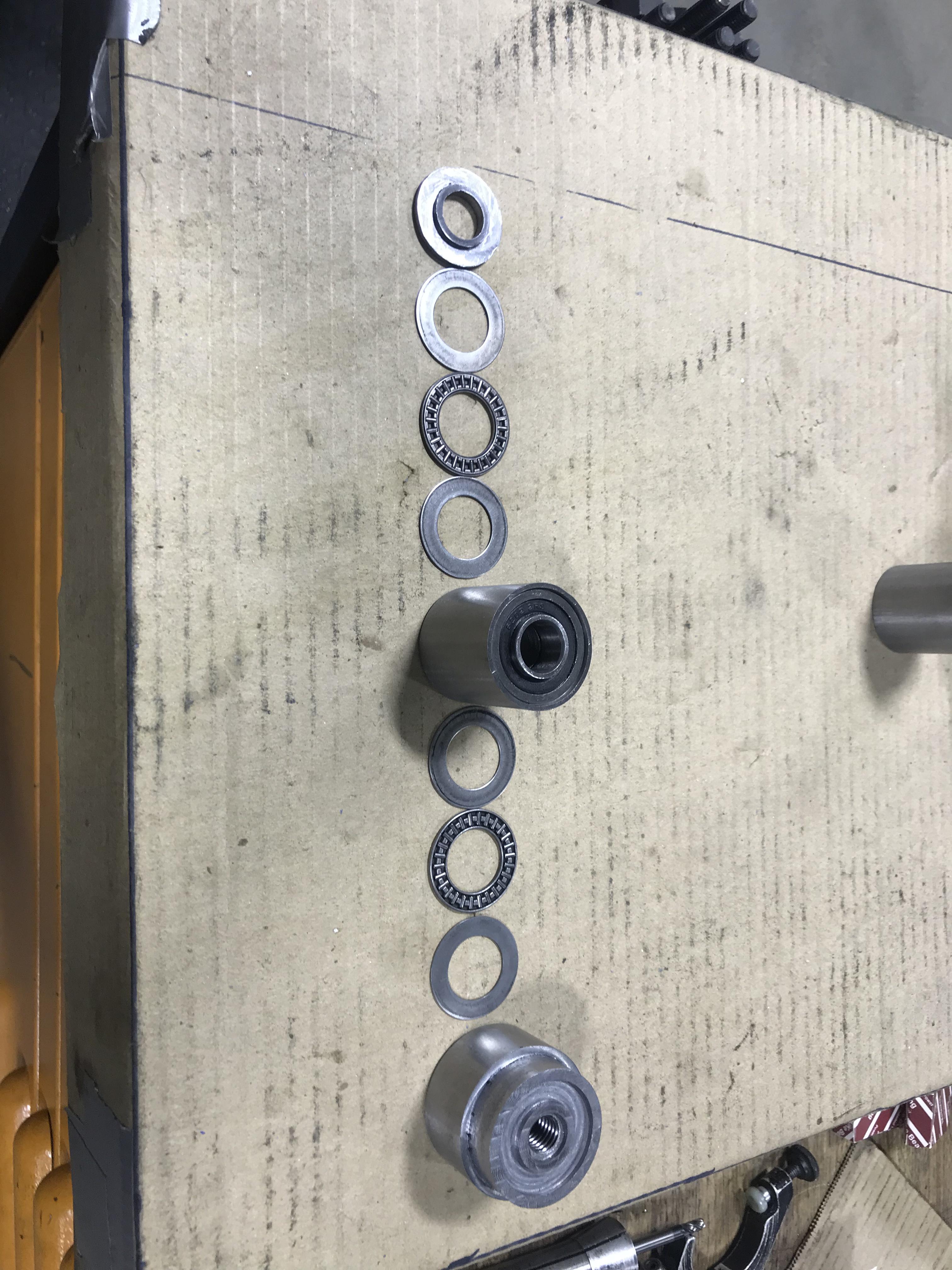
The stack up is From the top Down.
Stripper Bolt (Shear Strength of 82,000 Psi (Roughly 28,000 Pounds or shear force))
Harden Washer
Thrust Bearing
Harden Washer
Normal Ball Bearing
Mounting piece (Gets Welded into the Cantilever)
Normal Ball Bearing
Harden Washer
Thrust Bearing
Harden Washer
Mounting Blacking (will get mounted to the end of the tubing, (Tubing will likely be gusseted in the future)
-
Quote
-
Edit
-
-
Yeah this project was always intriguing, but has certainly caught more of my interest seeing things being modeled!
The shear area on that upper shock mount seems reasonable if you've got good penetration welds on both plates.
I think I saw the knuckles in a picture on a previous page, but are those a standard purchased component?
I've always thought it would be cool to do a ground up build like this, so I really look forward to the continuation of this!
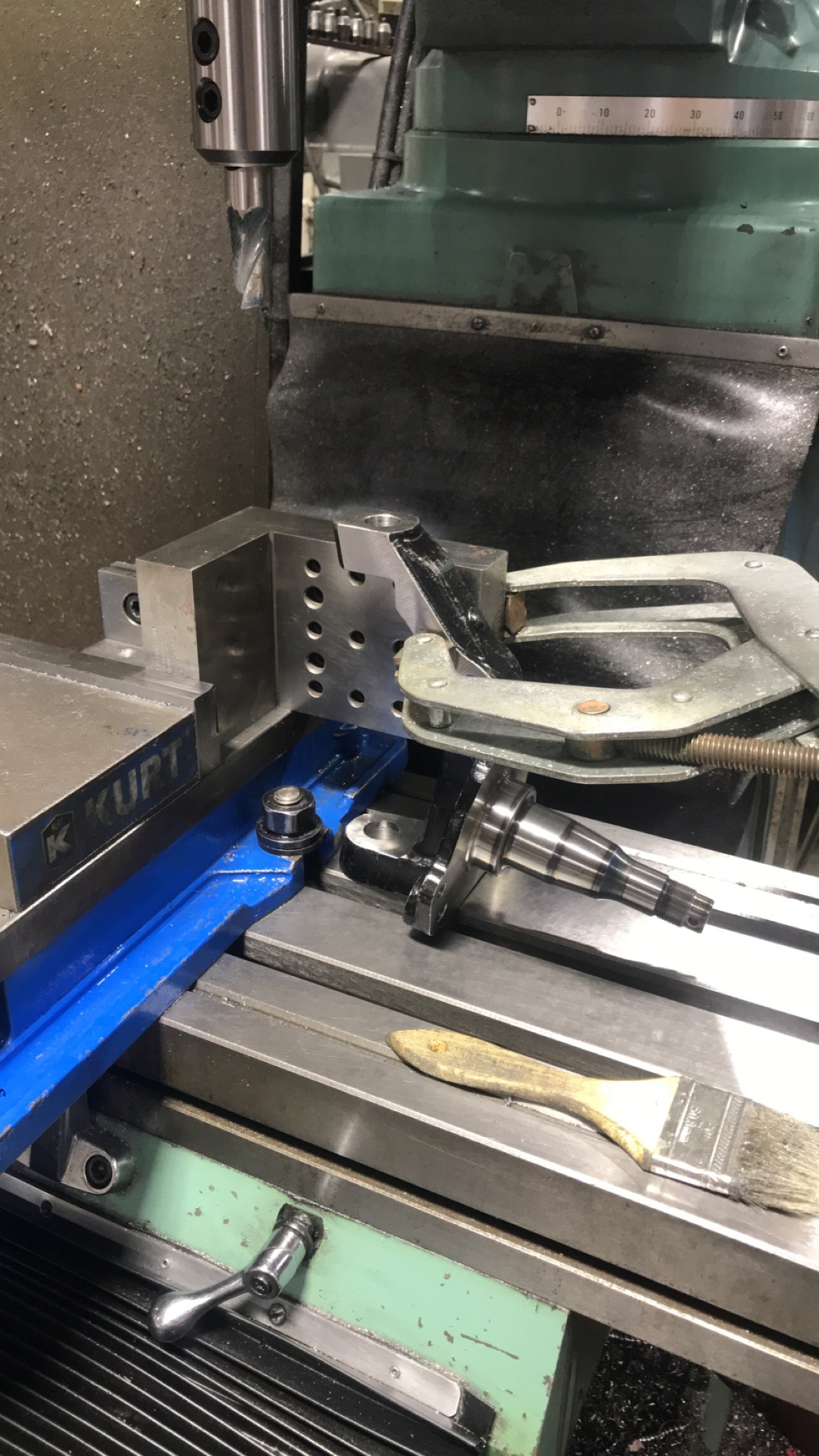
The Knuckle is a ford Pinto Spindle. Primarily Used in circle track applications.
-
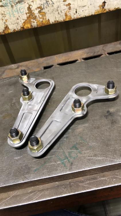
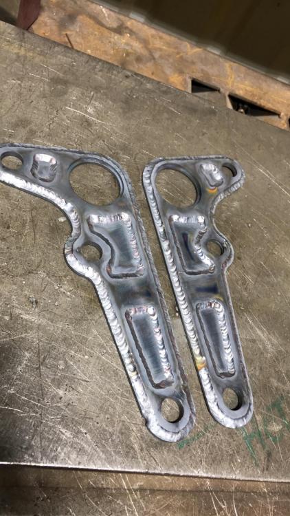
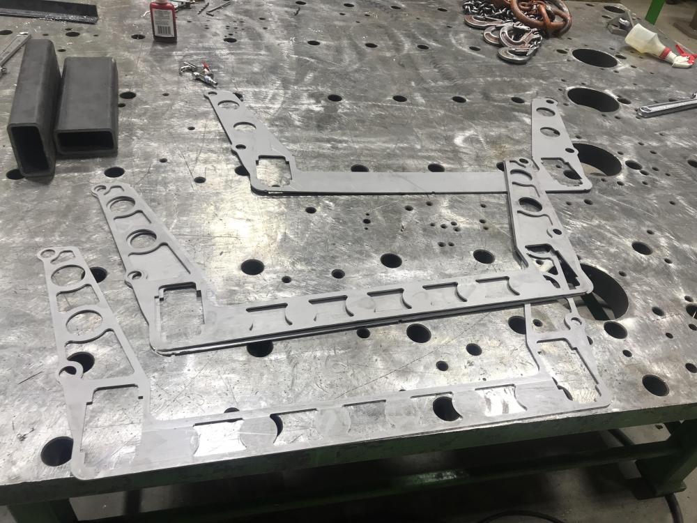
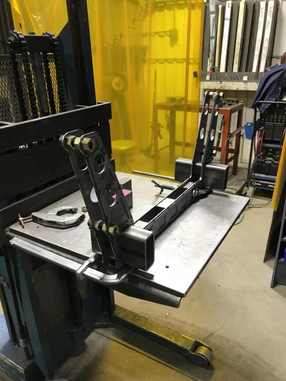
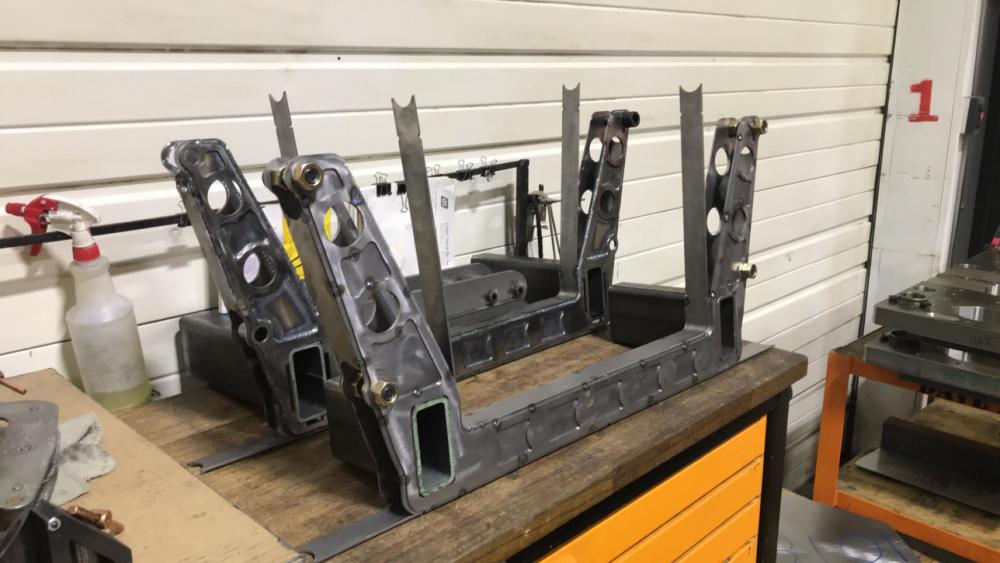
Quick update. with some actual fab work being done.
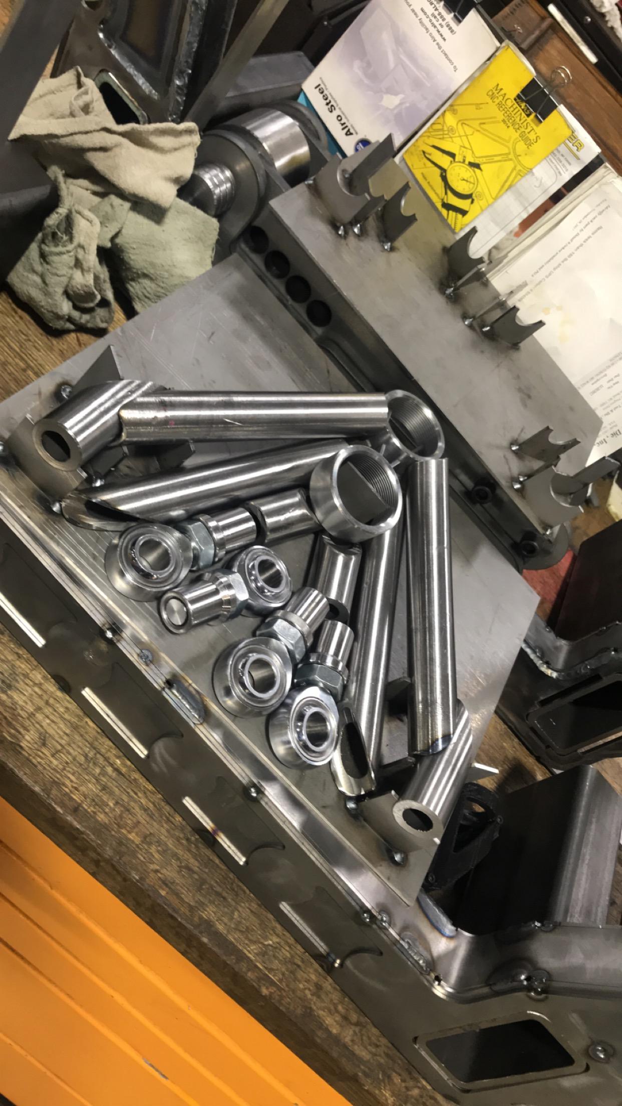
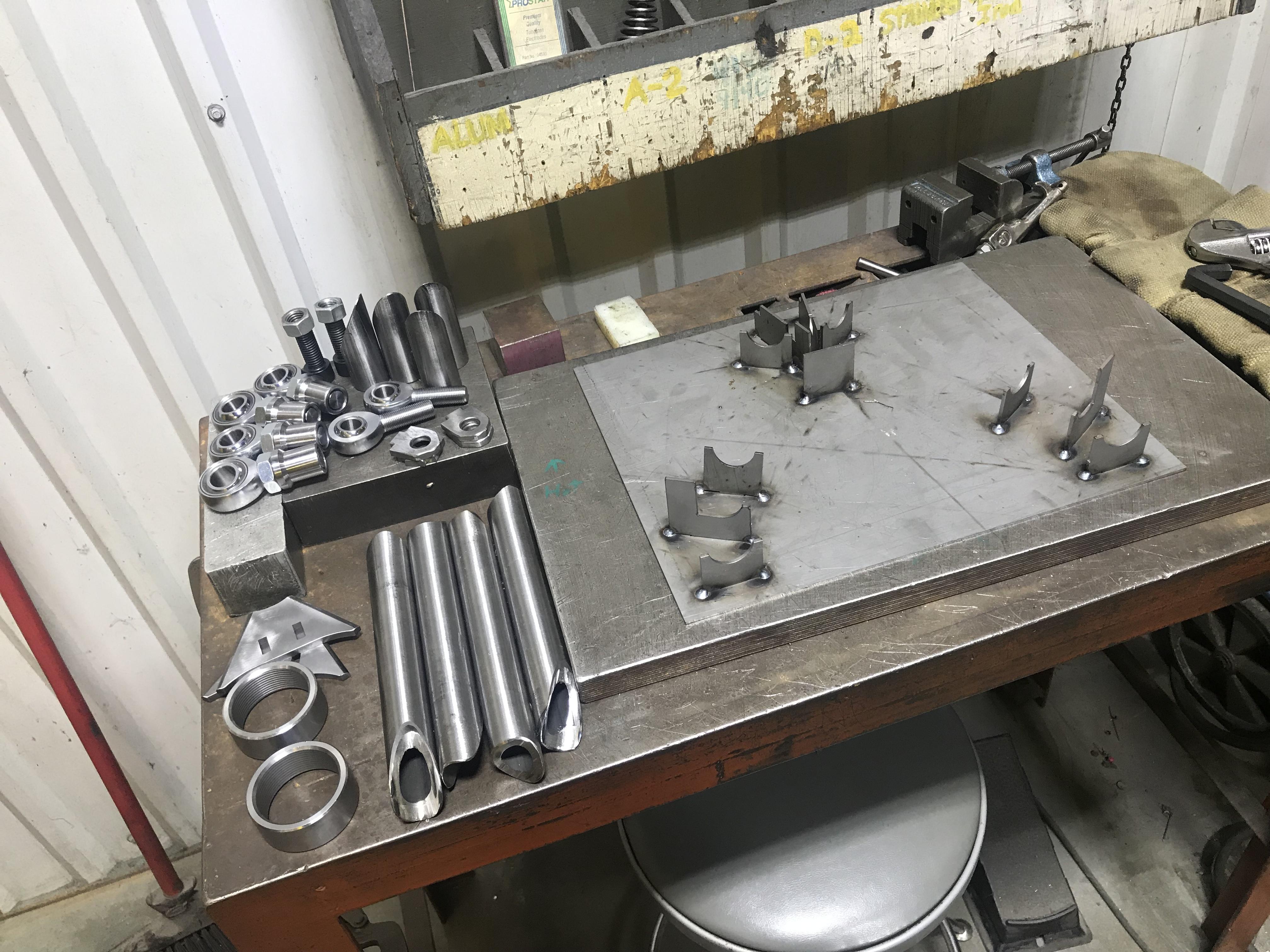
The past couple weeks I have been putting in some hours gettin some of the front frame done. I’m gonna attach some photos if you have any questions let me know. I’ll try to explain.
68146F60-B7C9-405D-9388-5EEEE2580392.MP4
3313FB85-223C-4B49-A9BD-F9EC8D2293C1.MOV 65AD28E0-186E-4B34-8577-045E1CC9E60F.MP4 9070B11F-FE72-4710-8BD4-5062AADA8845.MP4 BC8E10B8-81C0-4EF0-8CC0-98251DCCA8DB.MP4
-
-
I would not recommend using a stripper bolt in this manner. They are not intended to handle lateral forces and have a inherent stress riser at the base of the thread that is prone to failure.
Ideally you would support both sides of the pivot point from the subframe. if you must support it from one side a spool and bolt design will bend before failure, since it keeps the bolt in tension.
-
I would not recommend using a stripper bolt in this manner. They are not intended to handle lateral forces and have a inherent stress riser at the base of the thread that is prone to failure.
Ideally you would support both sides of the pivot point from the subframe. if you must support it from one side a spool and bolt design will bend before failure, since it keeps the bolt in tension.
I 100% agree with you. If you are using a Harden alloy shoulder bolt. But with that being said I will be mostly turning up a custom shoulder bolt . But any side load should be transferred to linear load with the thrust bearings. Not 100% transferred but lessened a great deal. I’m not saying you wrong in anyway and I will take any input I can.
-
CAD to Metal overnight. I like your fast pace.
What did you use to cut the parts? Waterjet?

https://www.instagram.com/_jdesigner_/ http://nevertoolow.tumblr.com/
🥳SOLD BMW E24 633CSI - BMW M30B32 🧪SOLD HCH ES9 - 1.3 LDA
👽BMW E30 325IC - Toyota 1JZ-GTE ⏰ HONDA EF9 CIVIC SI - JDM B18C5
☠️BMW E36 318i - Ford 5.0 FE302 🚴♂️ GT-Labomba - 26x2.75 Freeride
🤹♀️SOLD BMW E36/7 Z3 - BMW M54B25 🧓SOLD BMW E10 2002 - BMW M10M05 -
CAD to Metal overnight. I like your fast pace.
What did you use to cut the parts? Waterjet?
I work In a Tool Shop so i May have utilized Our CNC Laser.
I did have some of this work done Prior to posting the cad up date.
Its been after hours progress the past 2 weeks . I have 3 of the 4 Control Arms done. So you should see up-dates later this week.
Attachments:
-
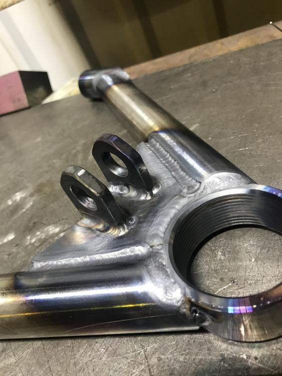
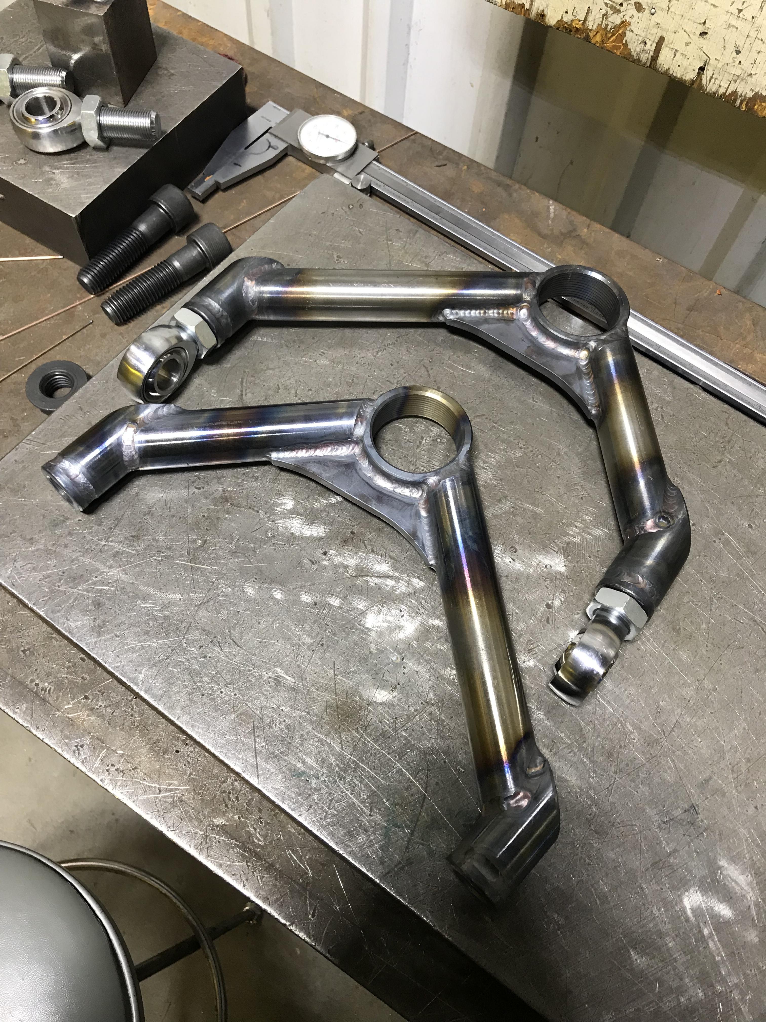
Update.
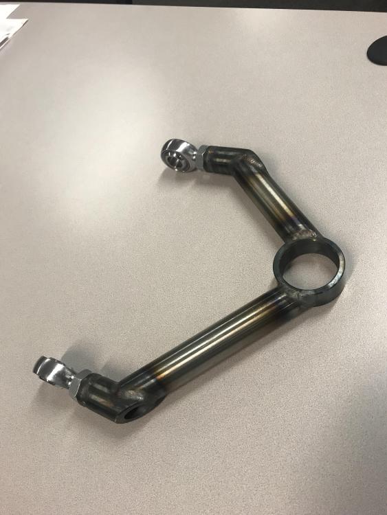
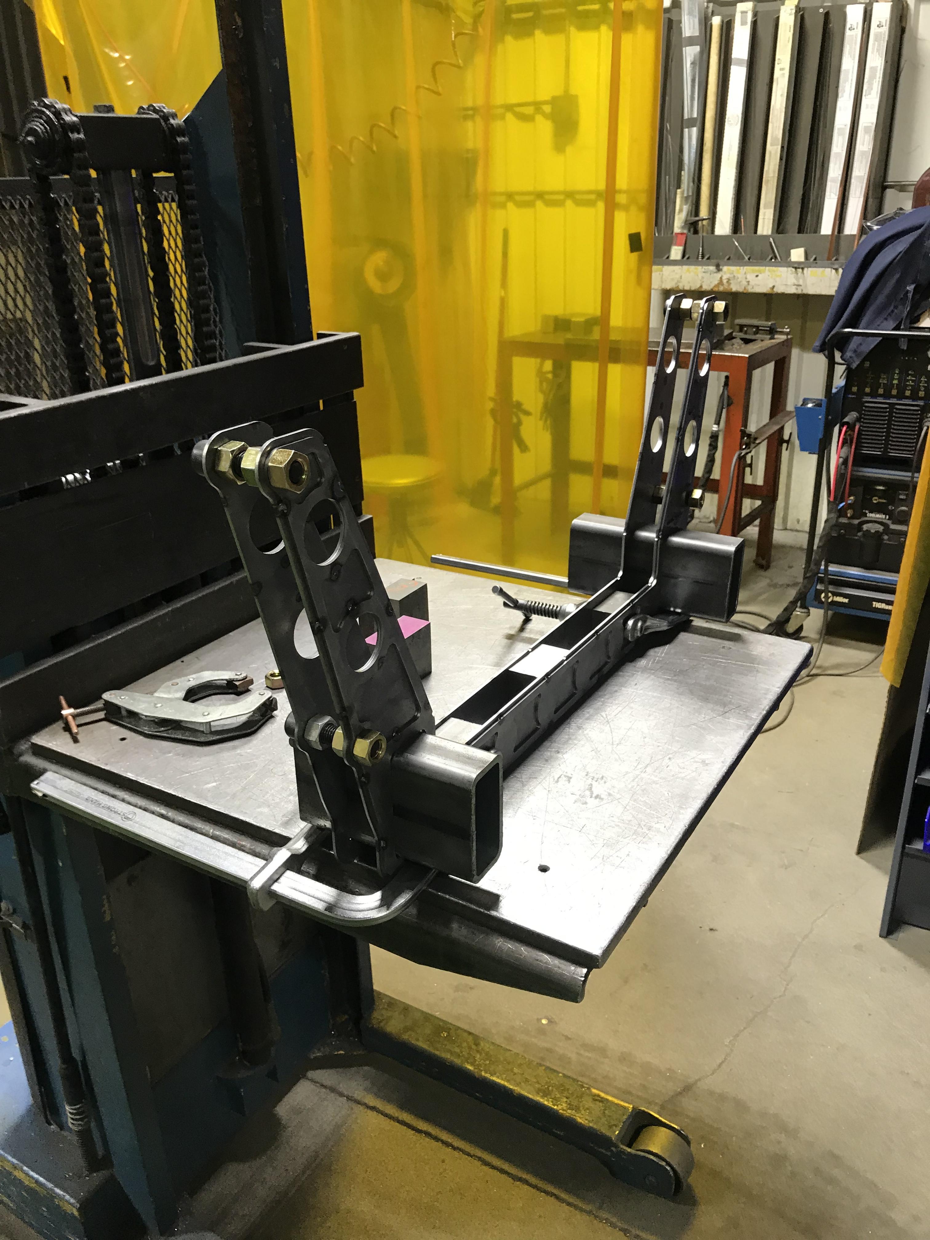
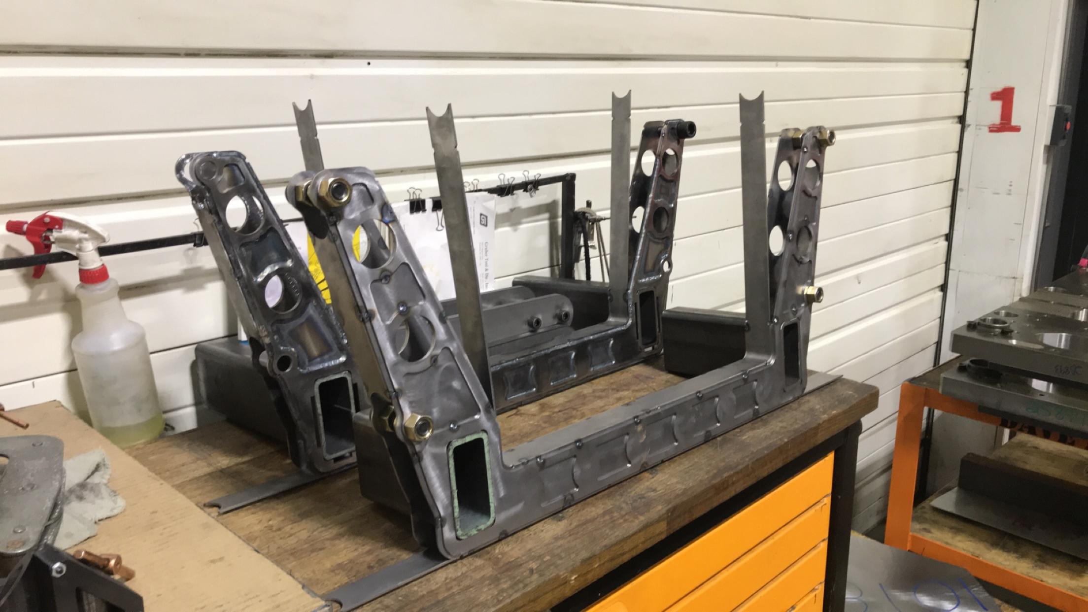
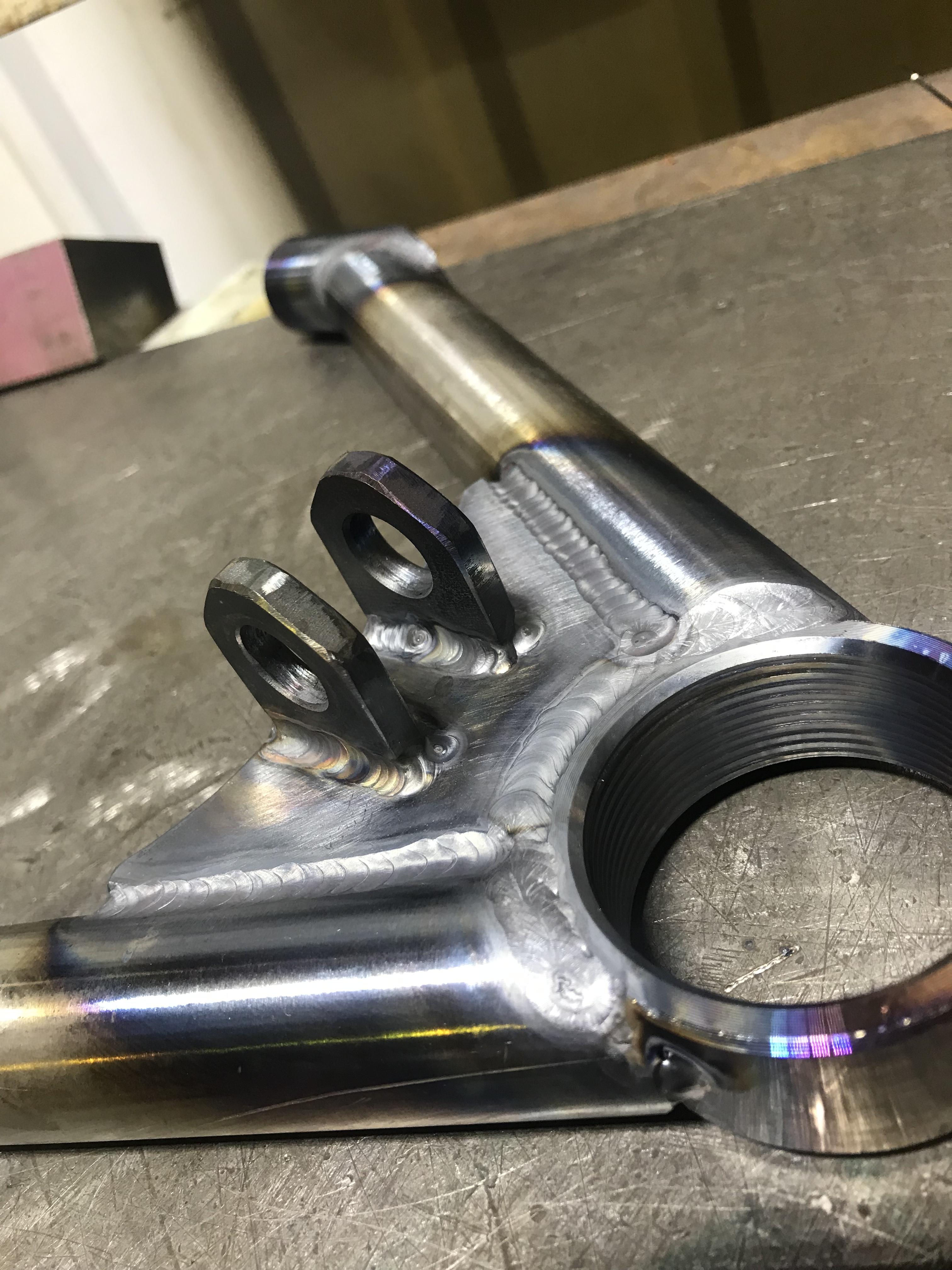
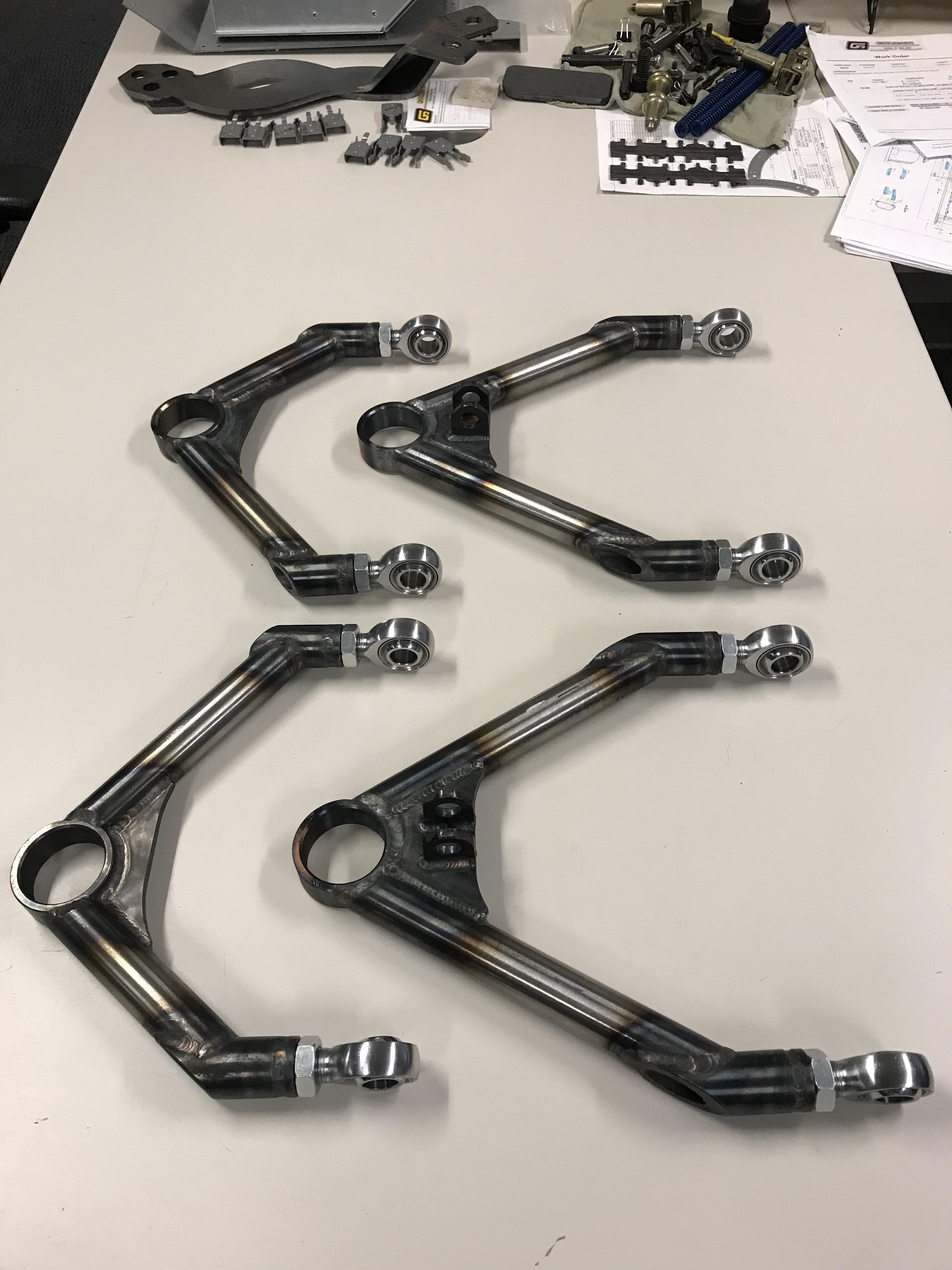
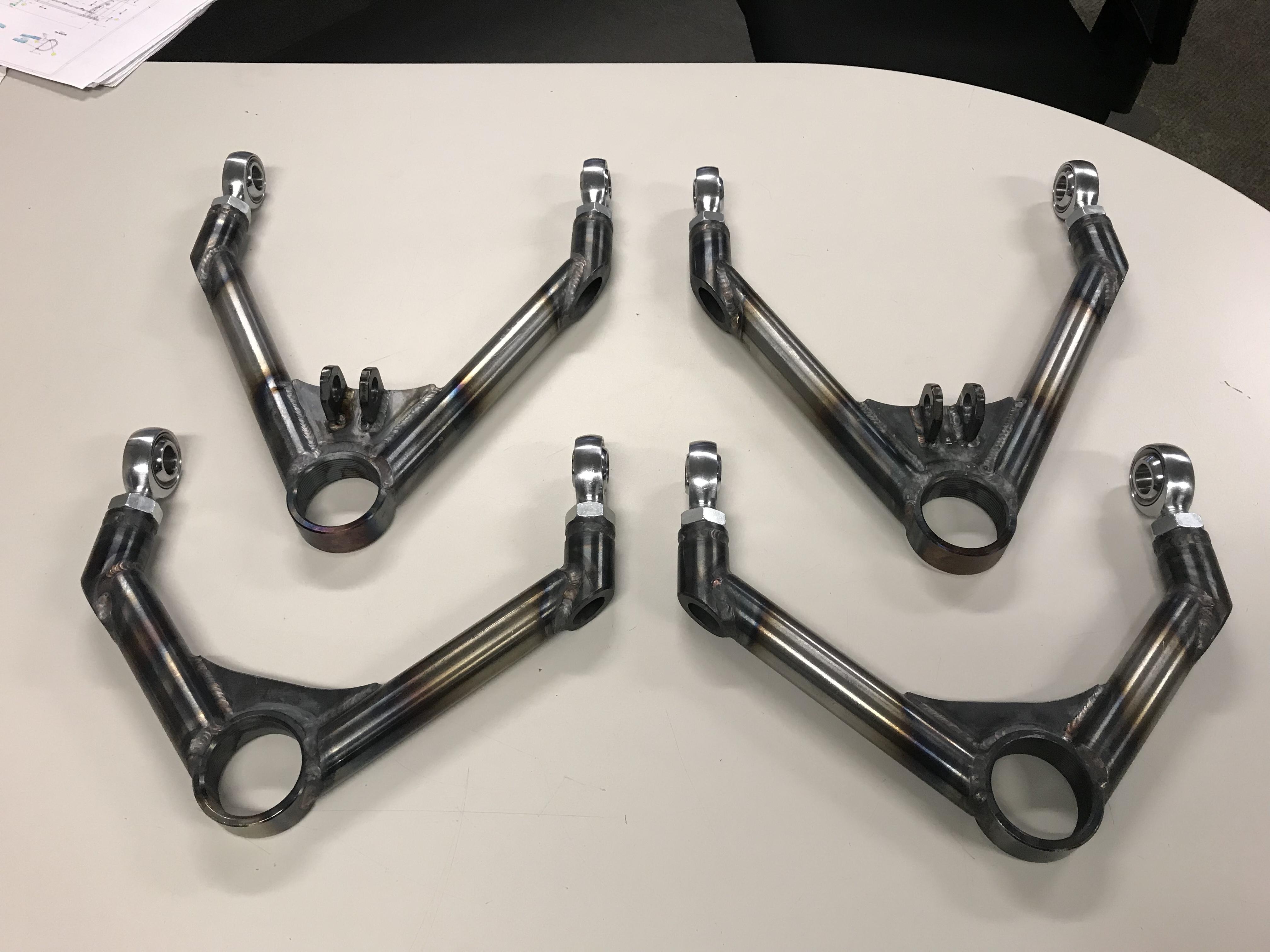
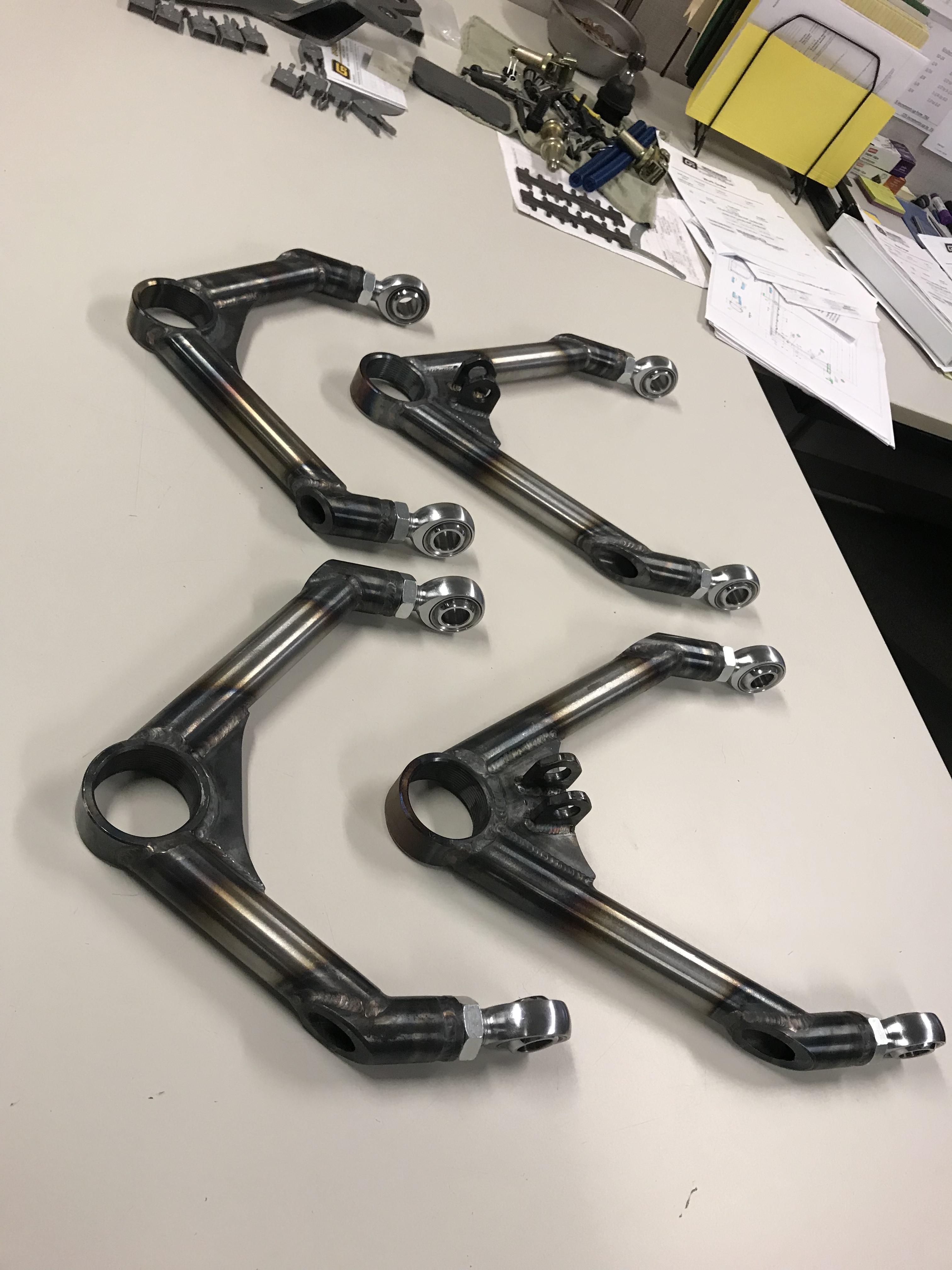
I gotta finish welding up the last control arm but here’s 3 of them.
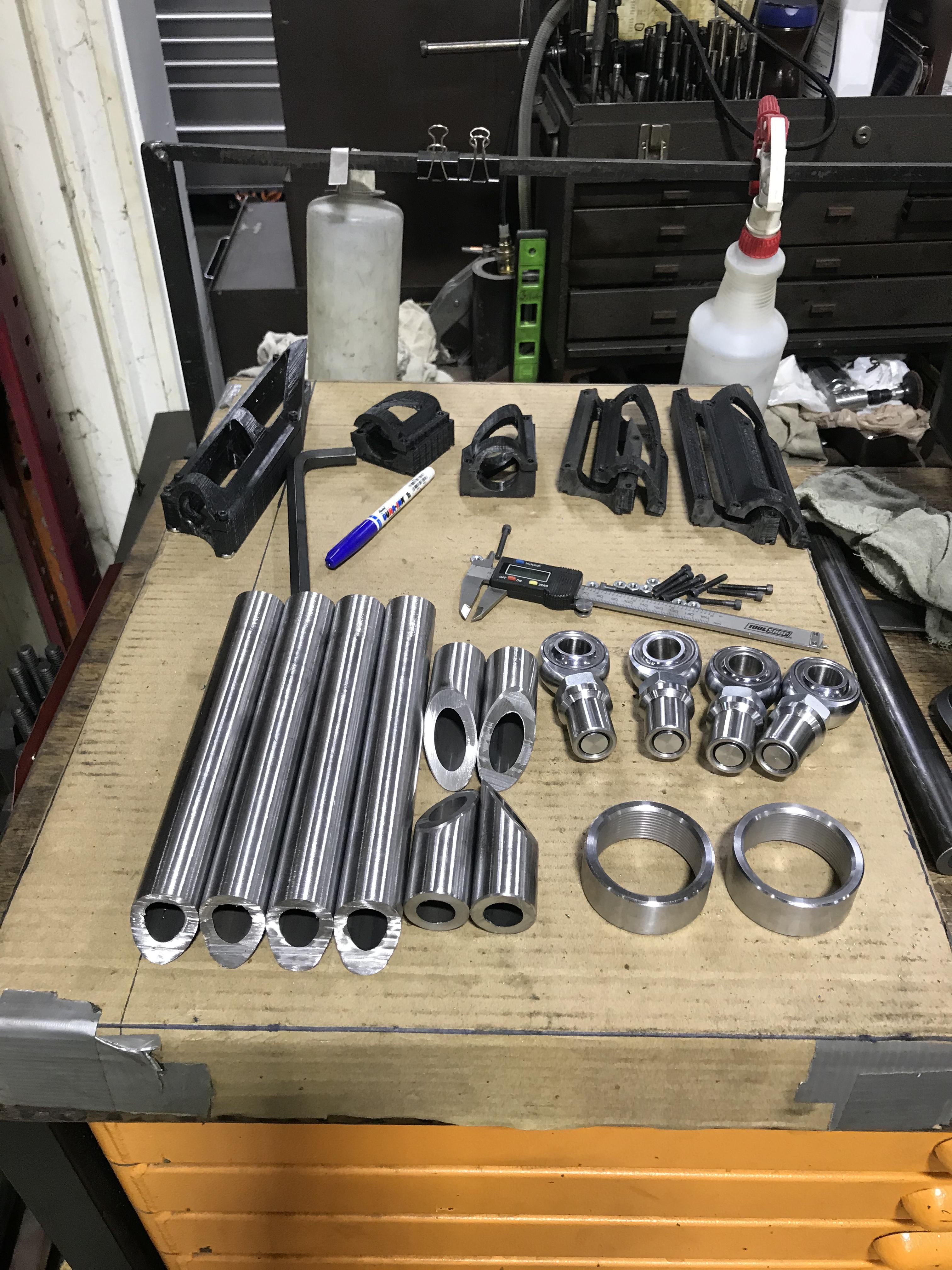
I used 3d printed jigs to replicate the tube lengths and made up a quick fixture.
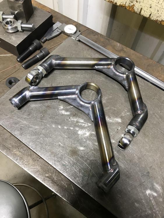
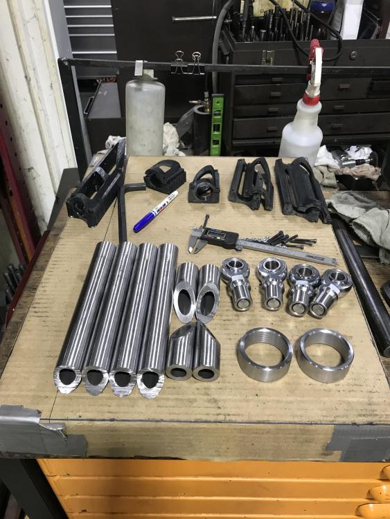
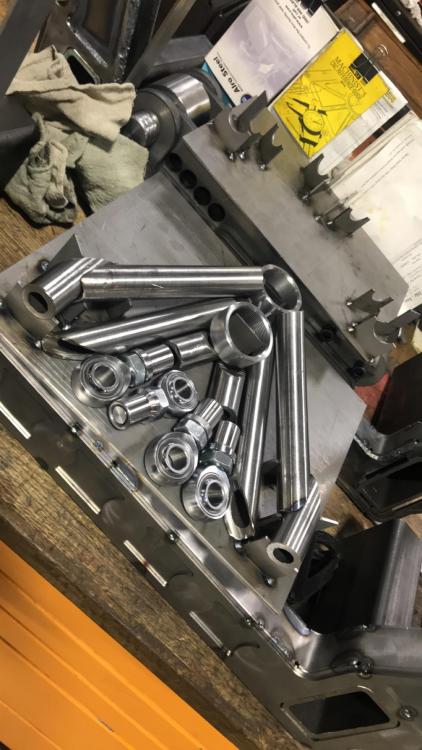
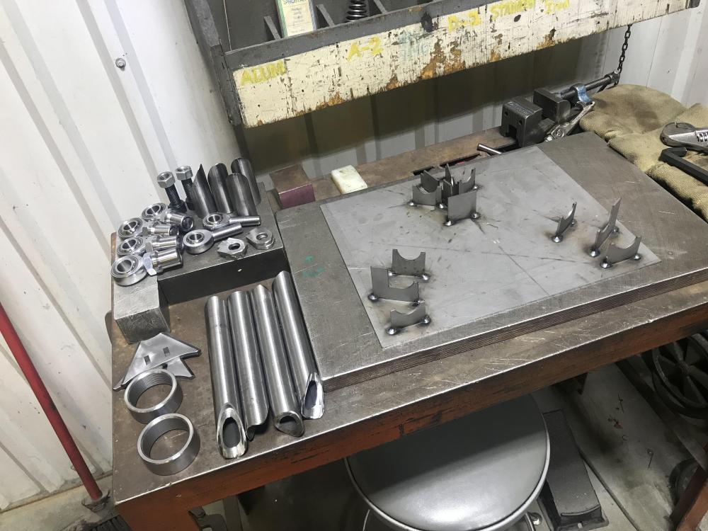
AD34B246-ADD6-4A4C-8B34-FB7E0FD25502.MP4
Attachments:
-
Chugga chugga. I cant wait to see the whole assembly!
https://www.instagram.com/_jdesigner_/ http://nevertoolow.tumblr.com/
🥳SOLD BMW E24 633CSI - BMW M30B32 🧪SOLD HCH ES9 - 1.3 LDA
👽BMW E30 325IC - Toyota 1JZ-GTE ⏰ HONDA EF9 CIVIC SI - JDM B18C5
☠️BMW E36 318i - Ford 5.0 FE302 🚴♂️ GT-Labomba - 26x2.75 Freeride
🤹♀️SOLD BMW E36/7 Z3 - BMW M54B25 🧓SOLD BMW E10 2002 - BMW M10M05 -
Chugga chugga. I cant wait to see the whole assembly!
I got a lot of welding to do on the subframes but hopefully soon. My ball joints are on back order sadly.
-
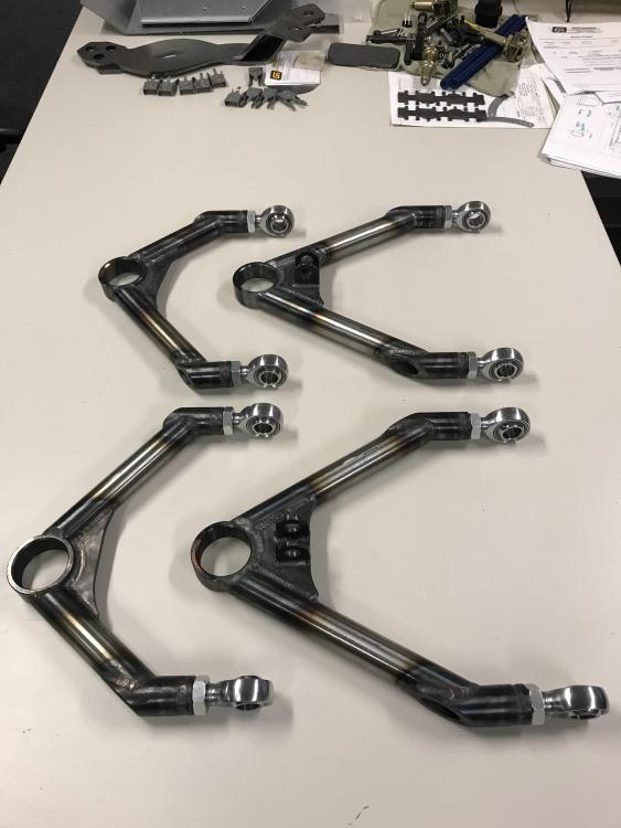
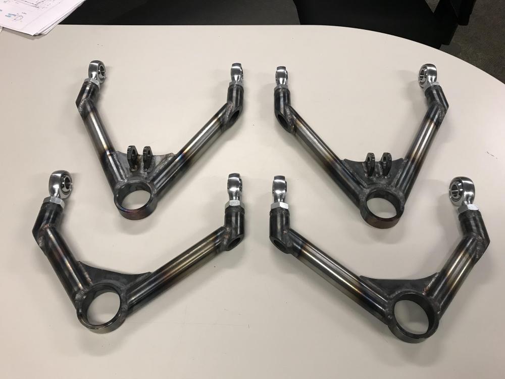
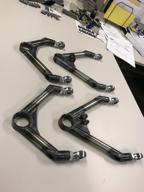
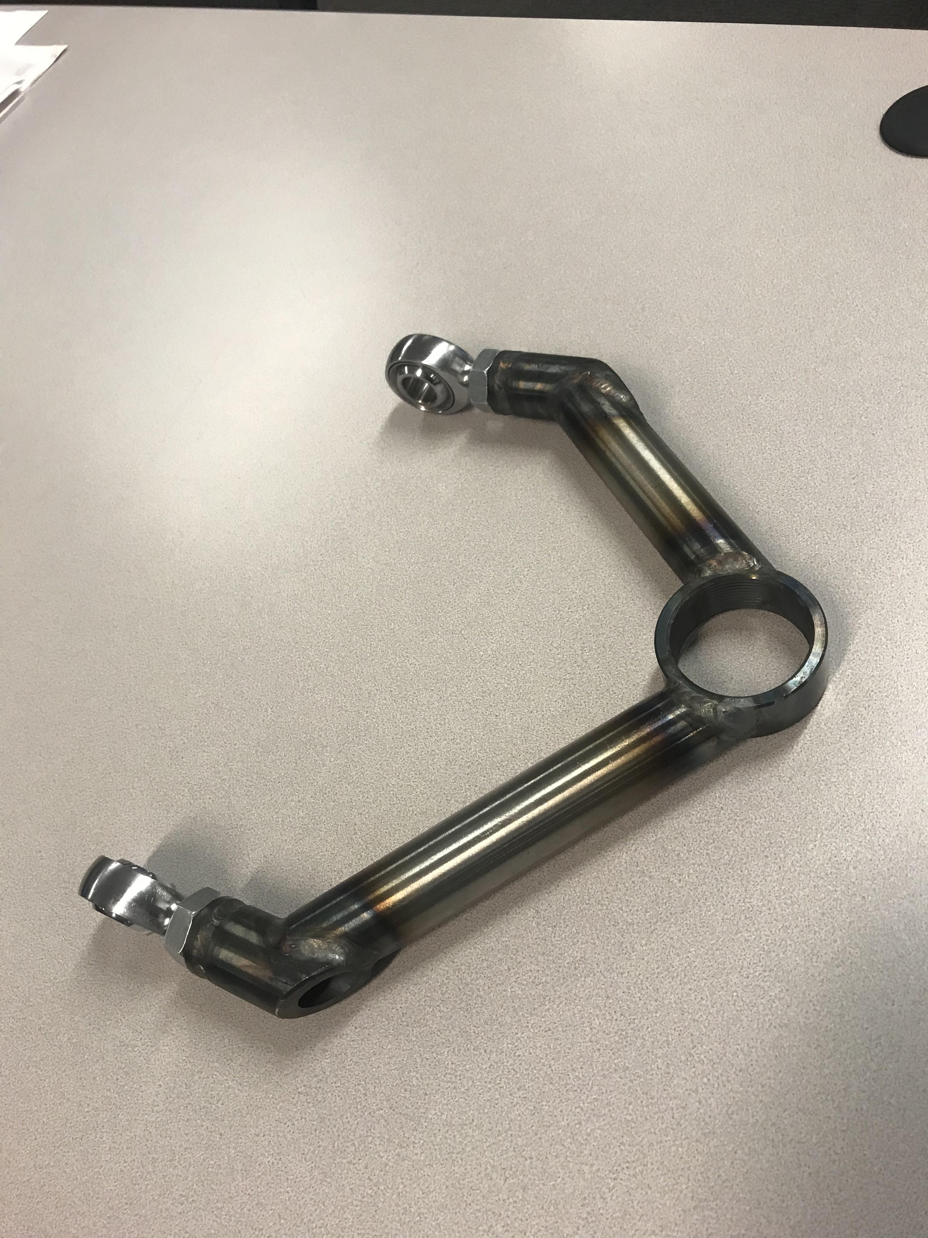
All 4 done and ready to go. They will be powder coated in the future but first I gotta get some mock-up done.
-
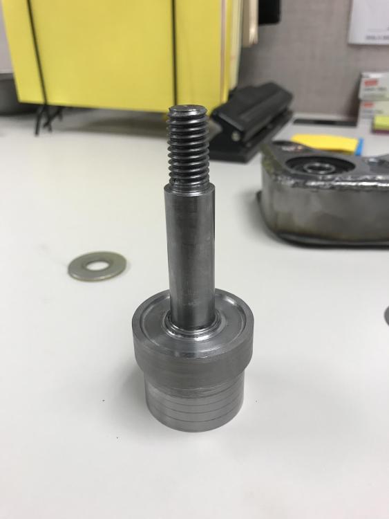
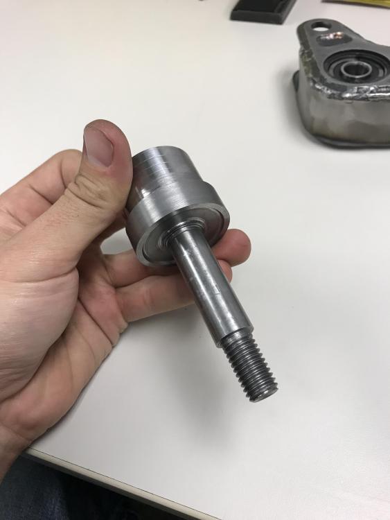
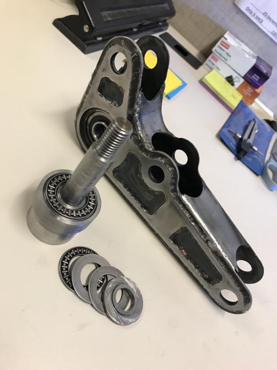
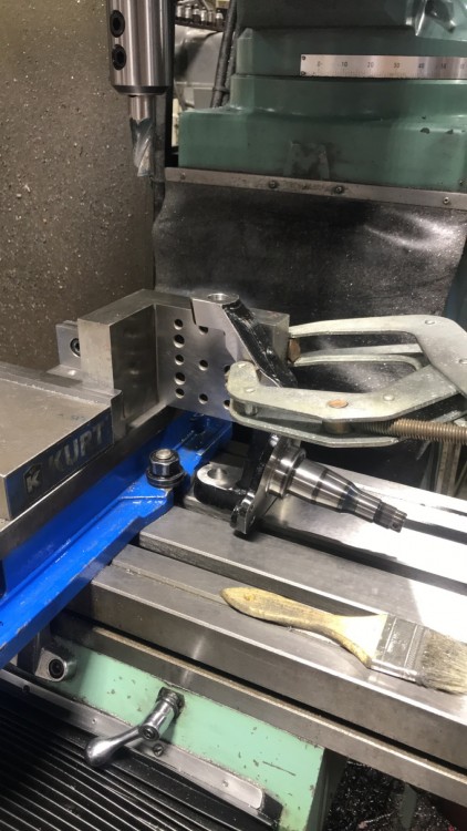
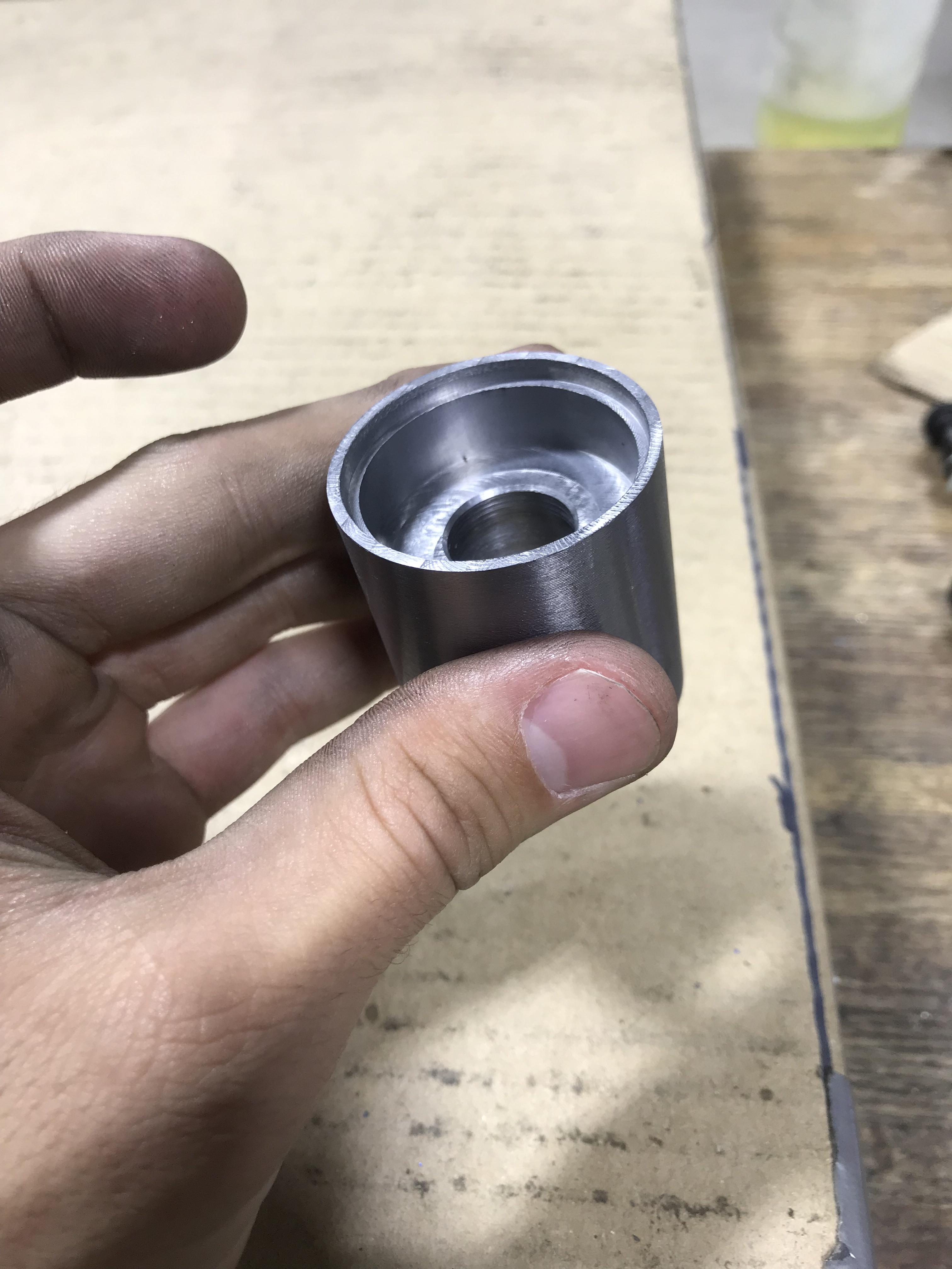
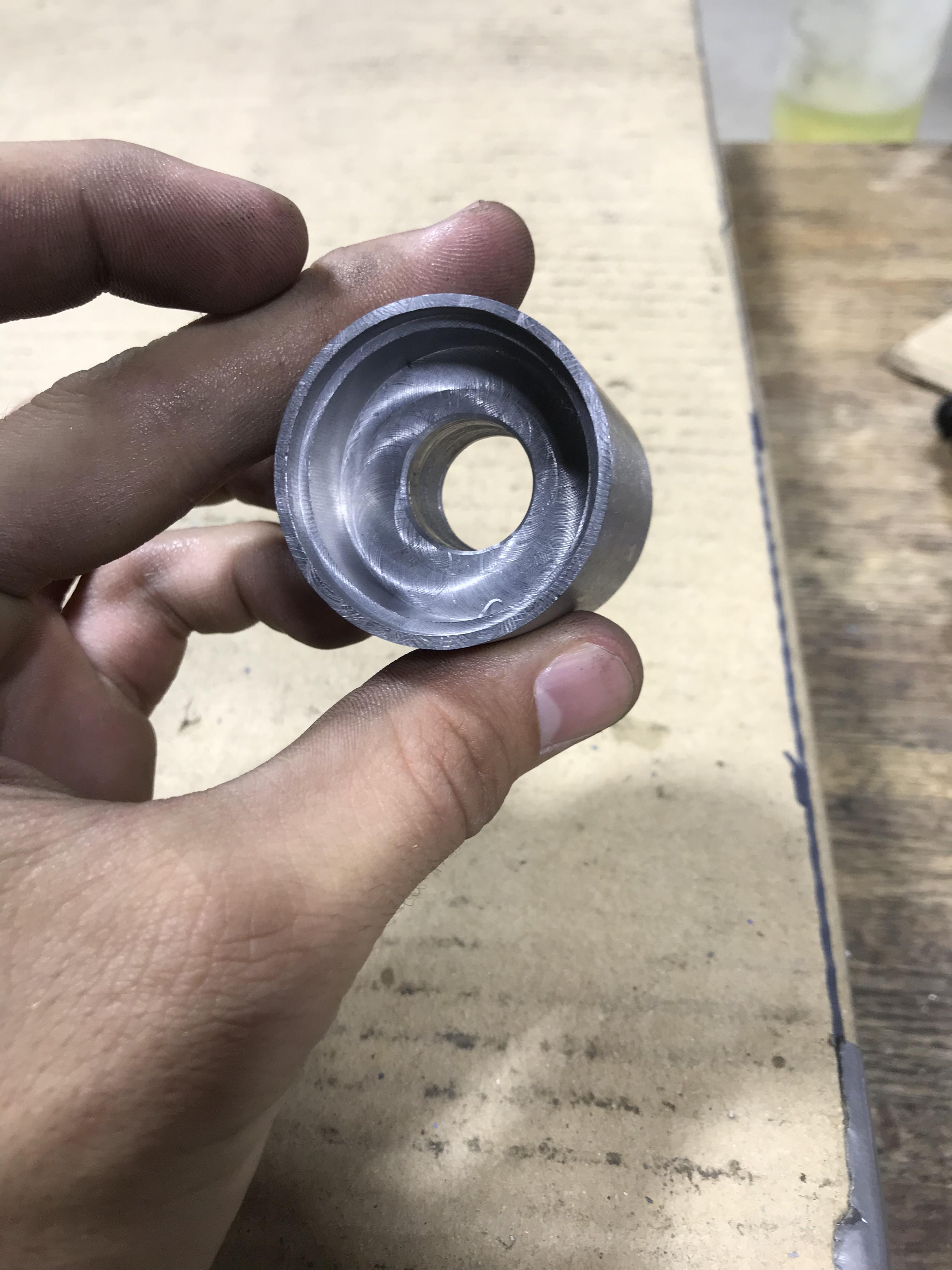
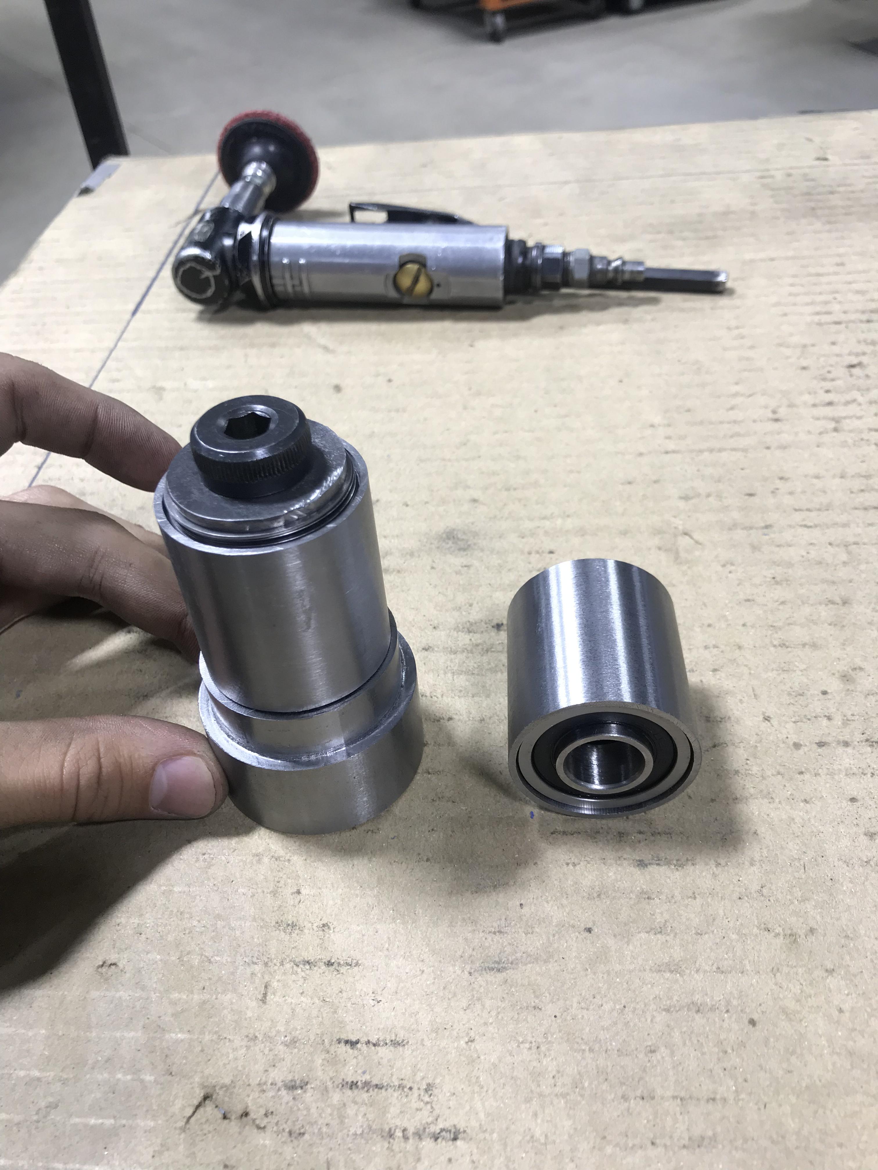
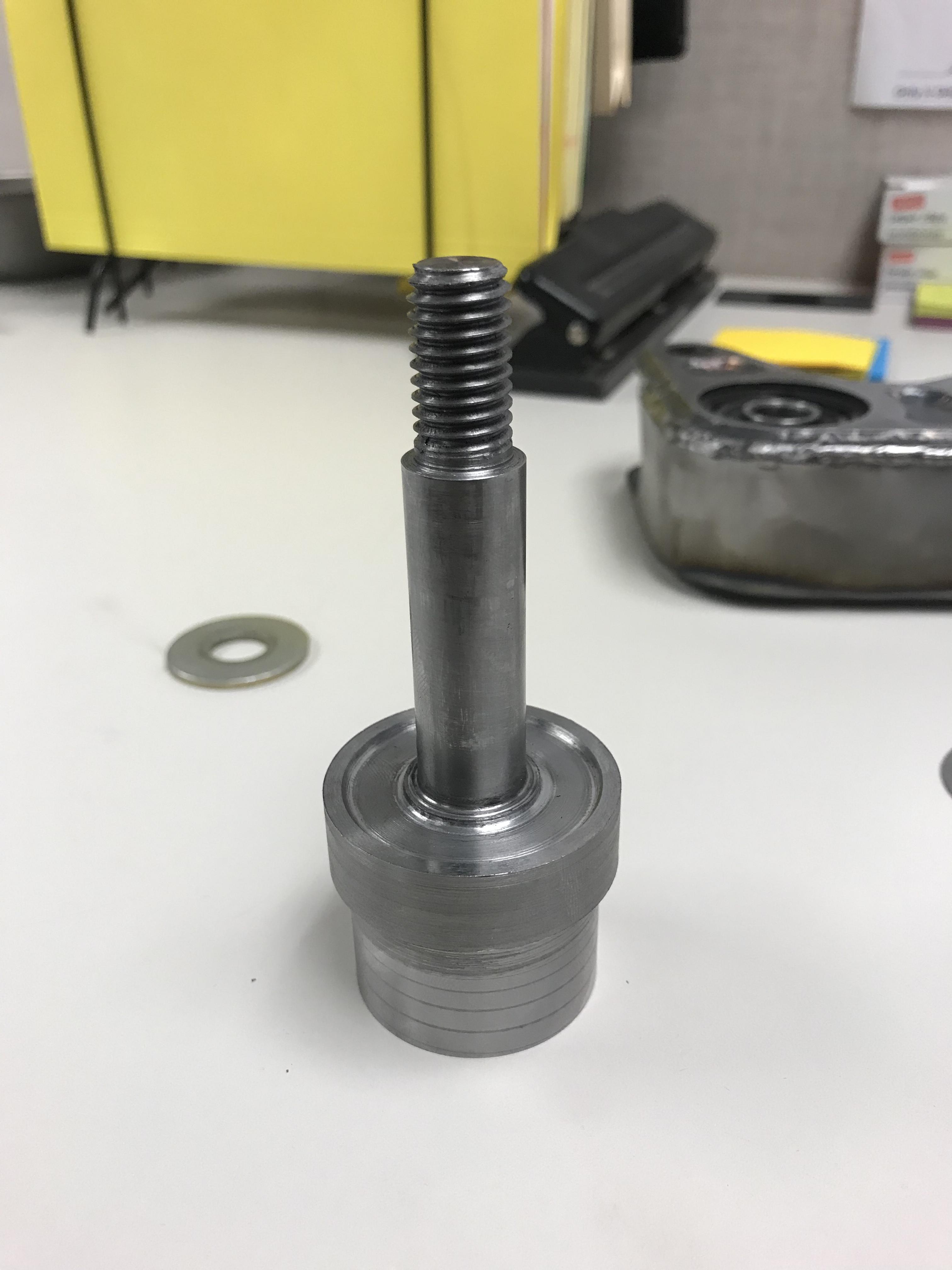
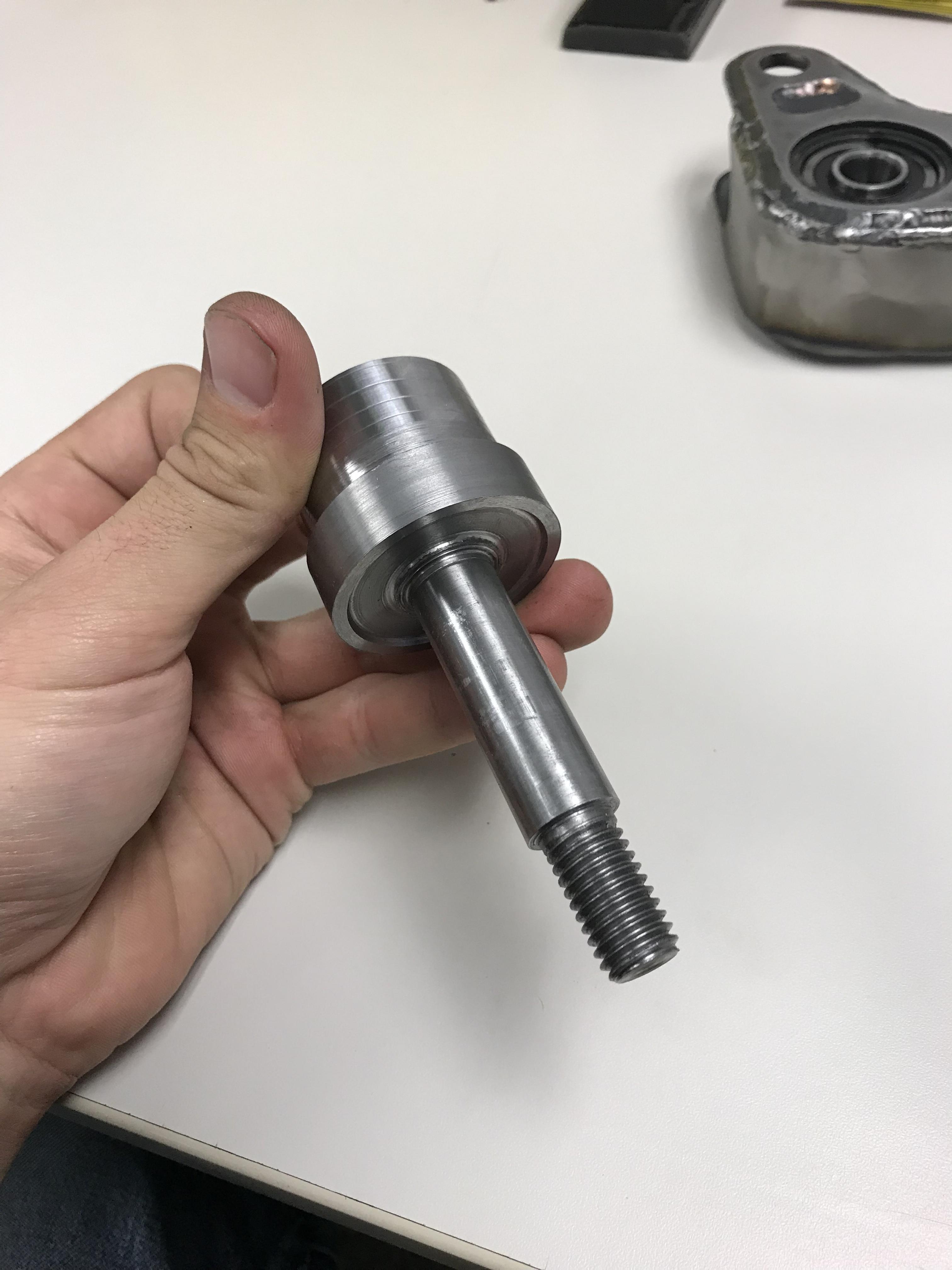
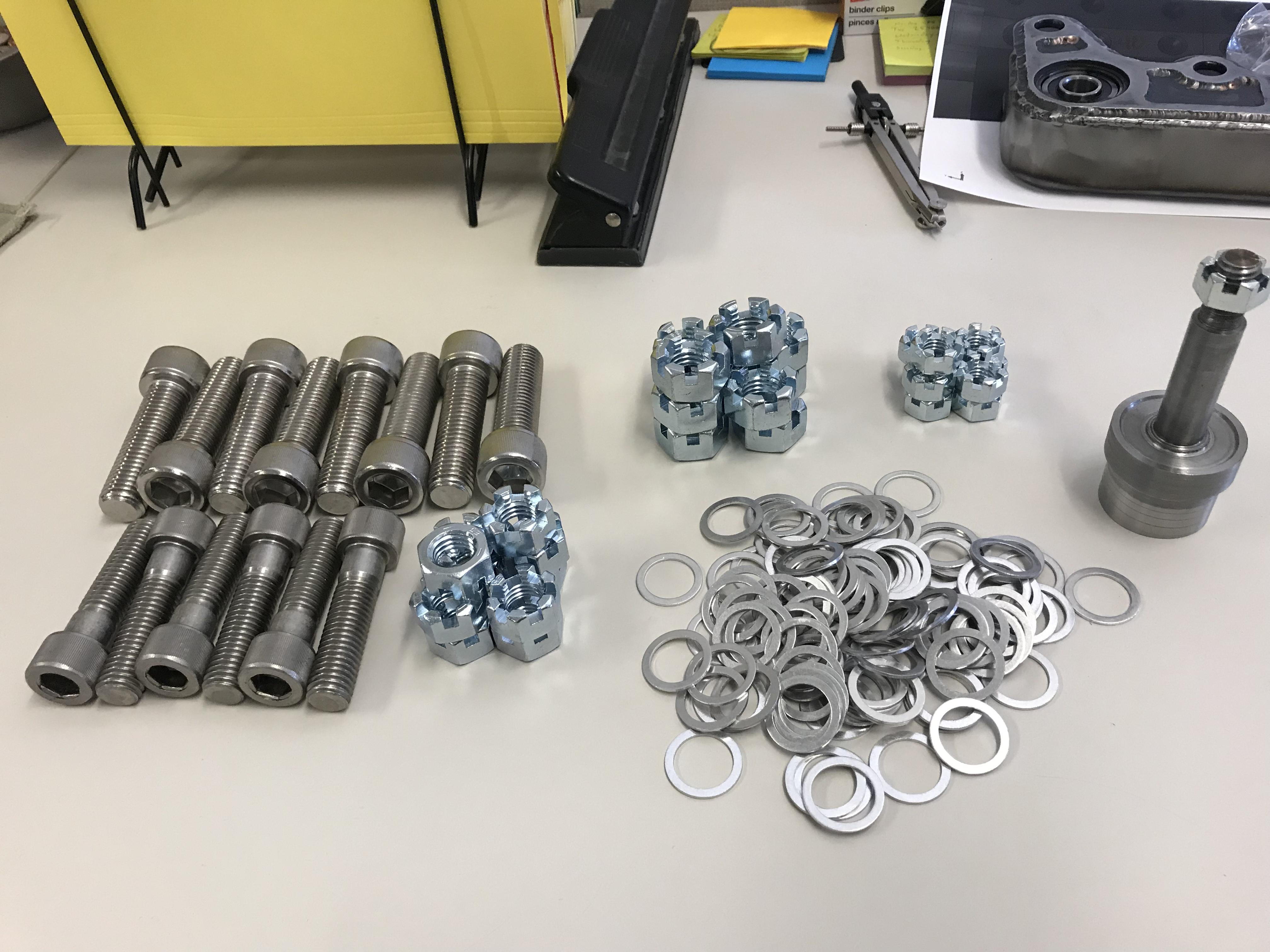
With some help from RobZR. I believe we have reached a much safer option from using a shoulder bolt. I made up this spindle design last night. This will have a castle nut and cotter pin in its end form. I did tighten it all down and I’m very pleased with how it turned out. zero play.

-
Great work man! You may also consider using oil impregnated solid thrust washers instead of roller bearing thrust washers if the loads are low enough and you want to improve environmental protection.
The castle nut is a great idea
I would like to possible try 3d Printing some bushings for weather protection. Out of some soft filament. Or Nylon
-
Quick up date.
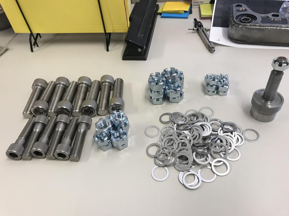
Got some of my hardware to assemble my front end just waiting on ball joints and got a finish up some welding
-
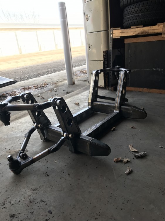
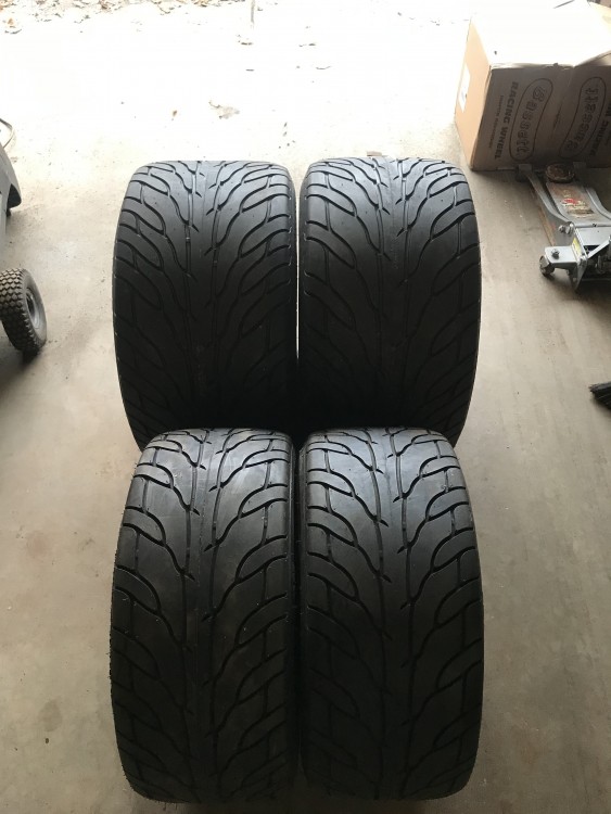
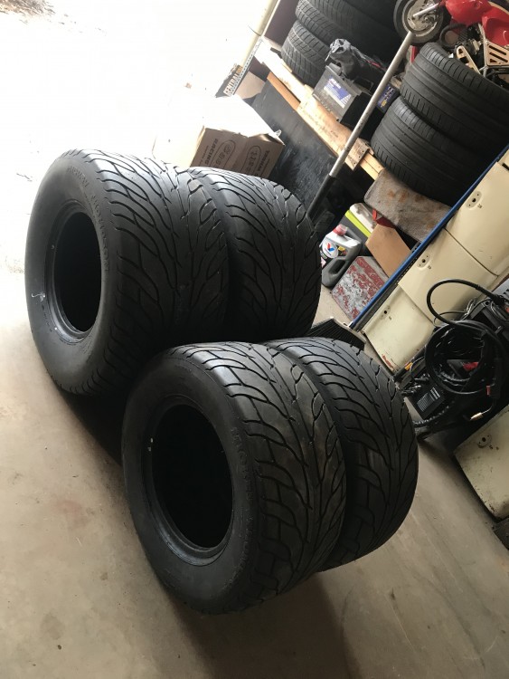
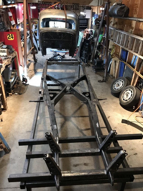
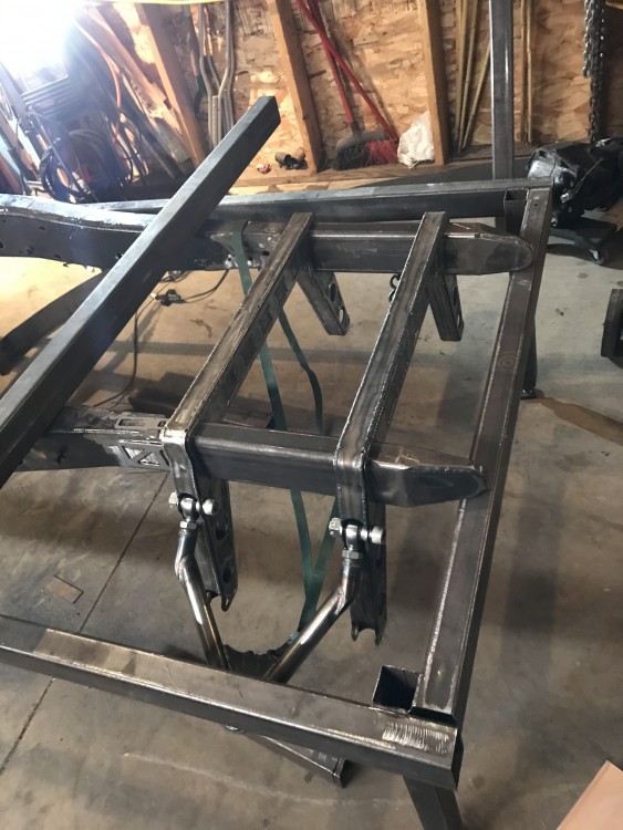
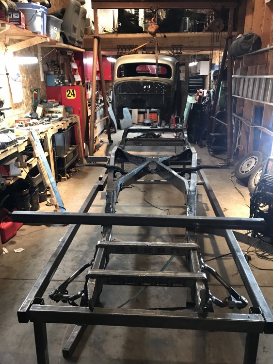
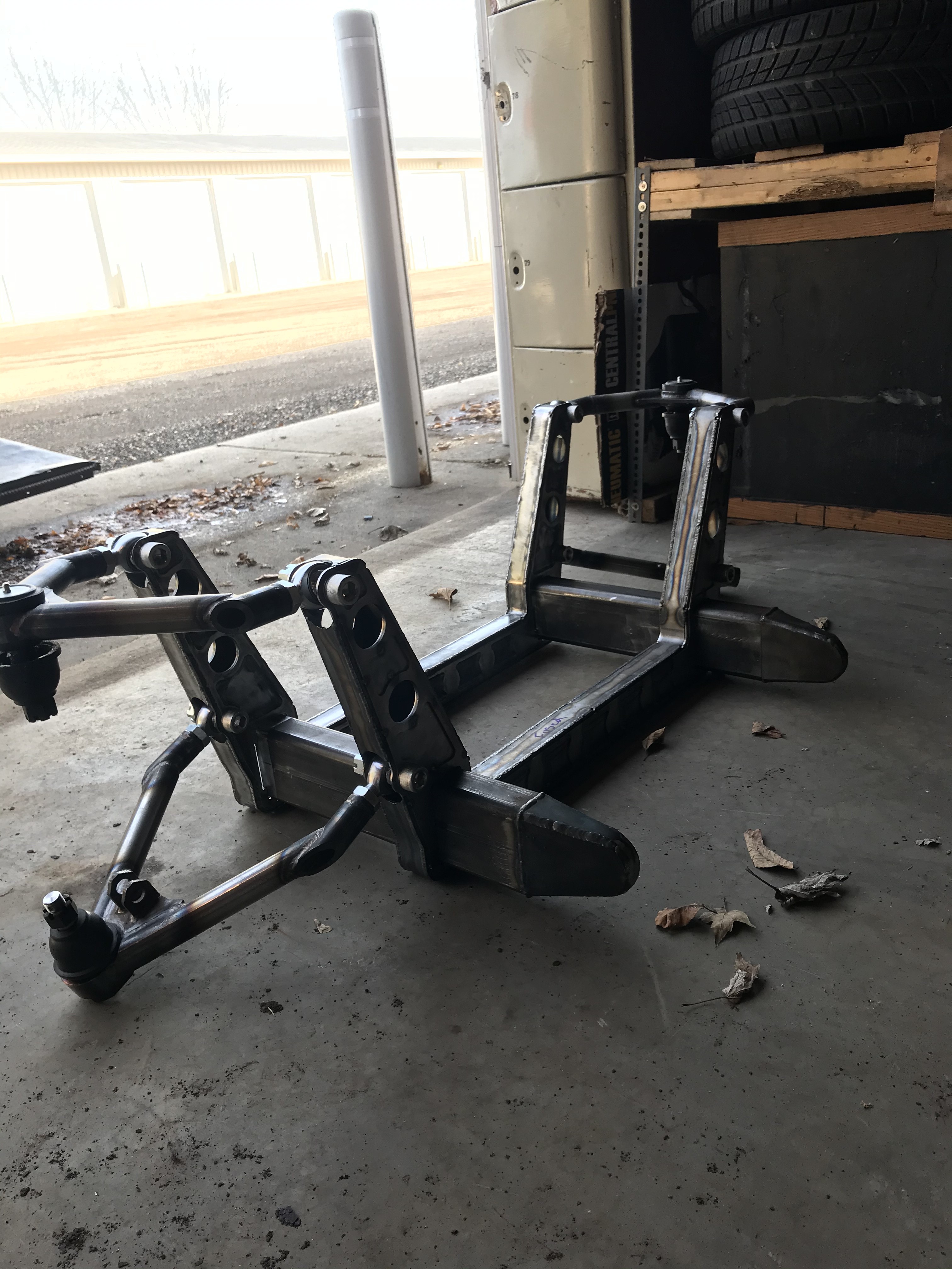
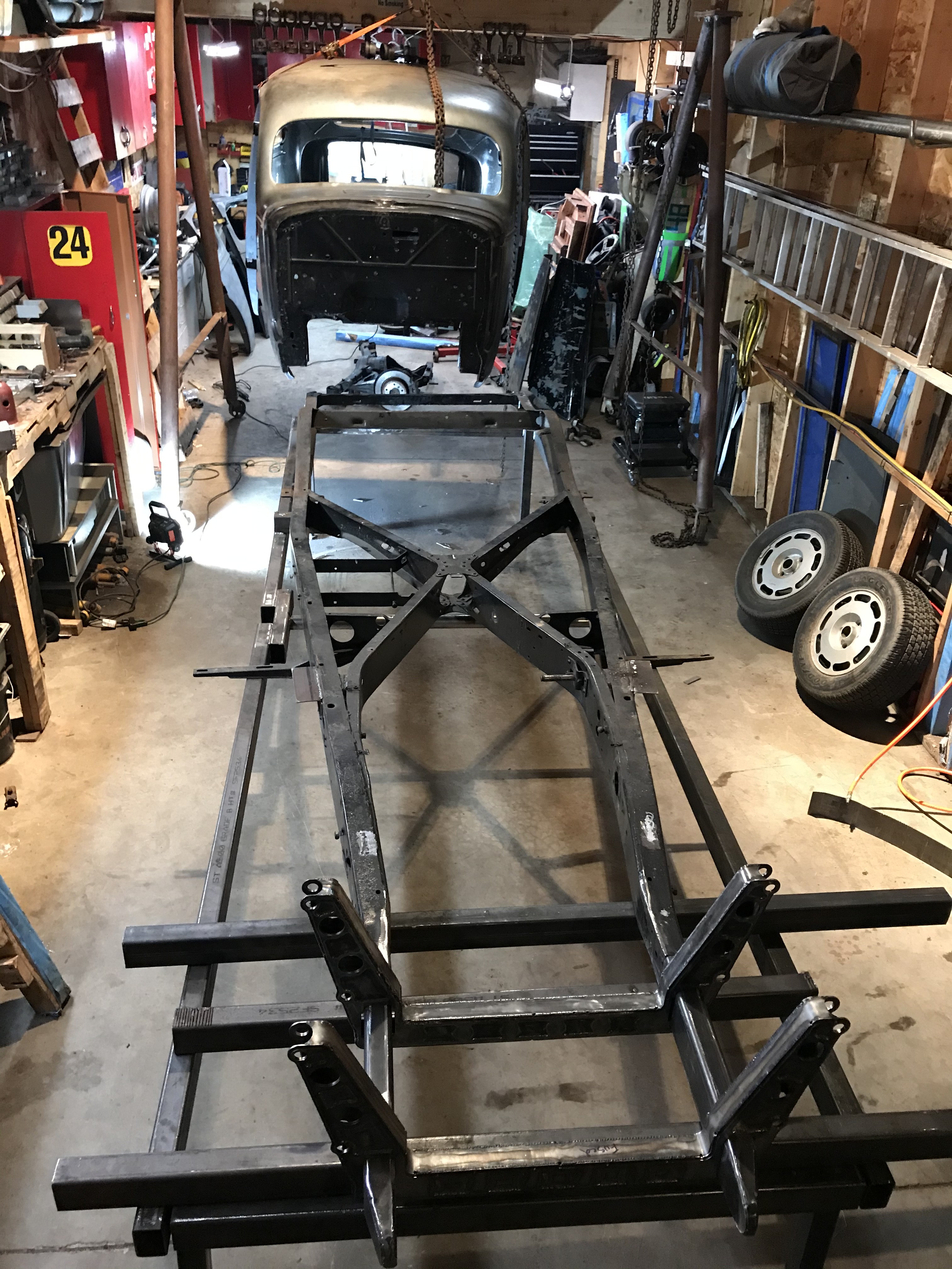
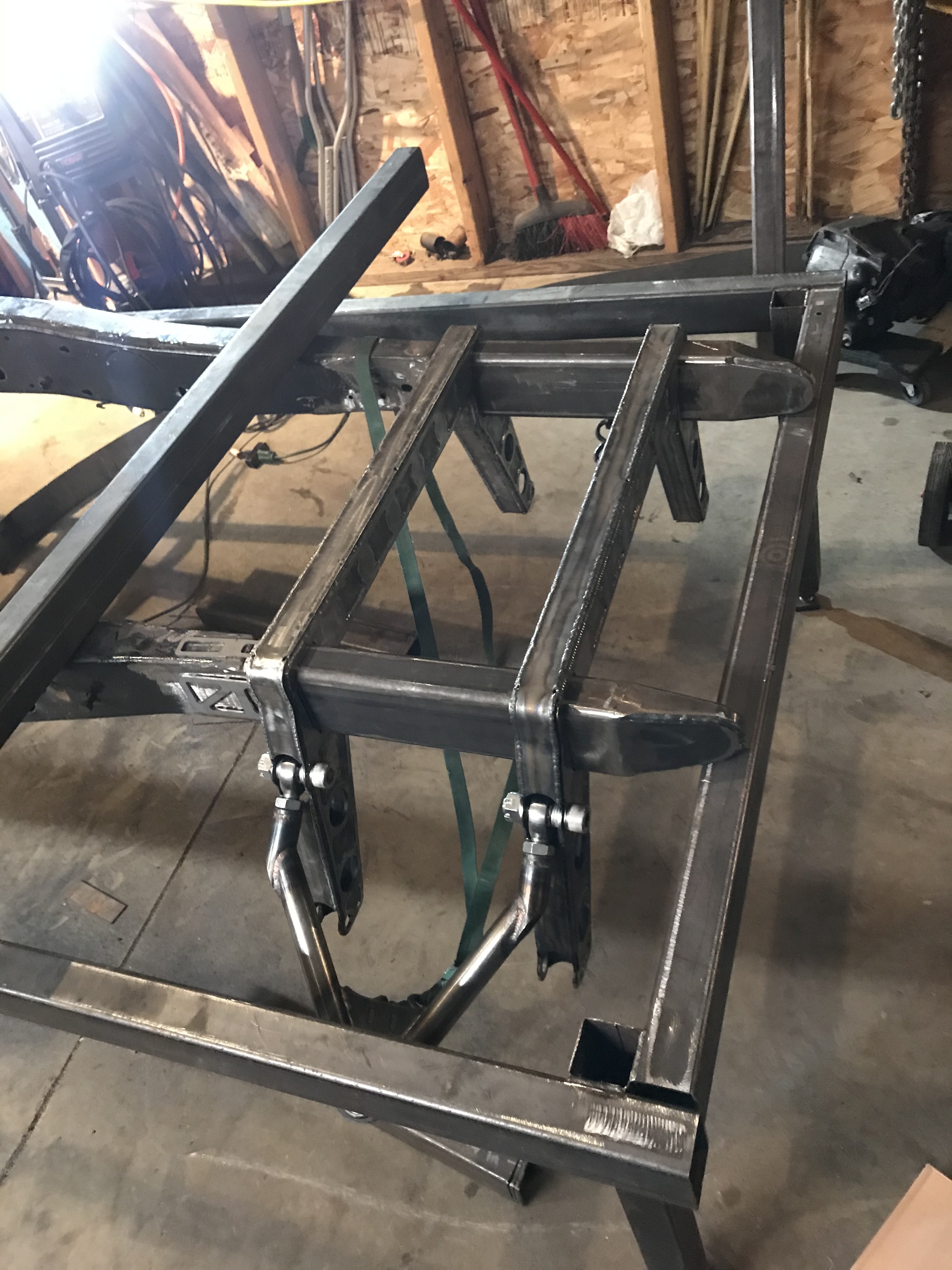
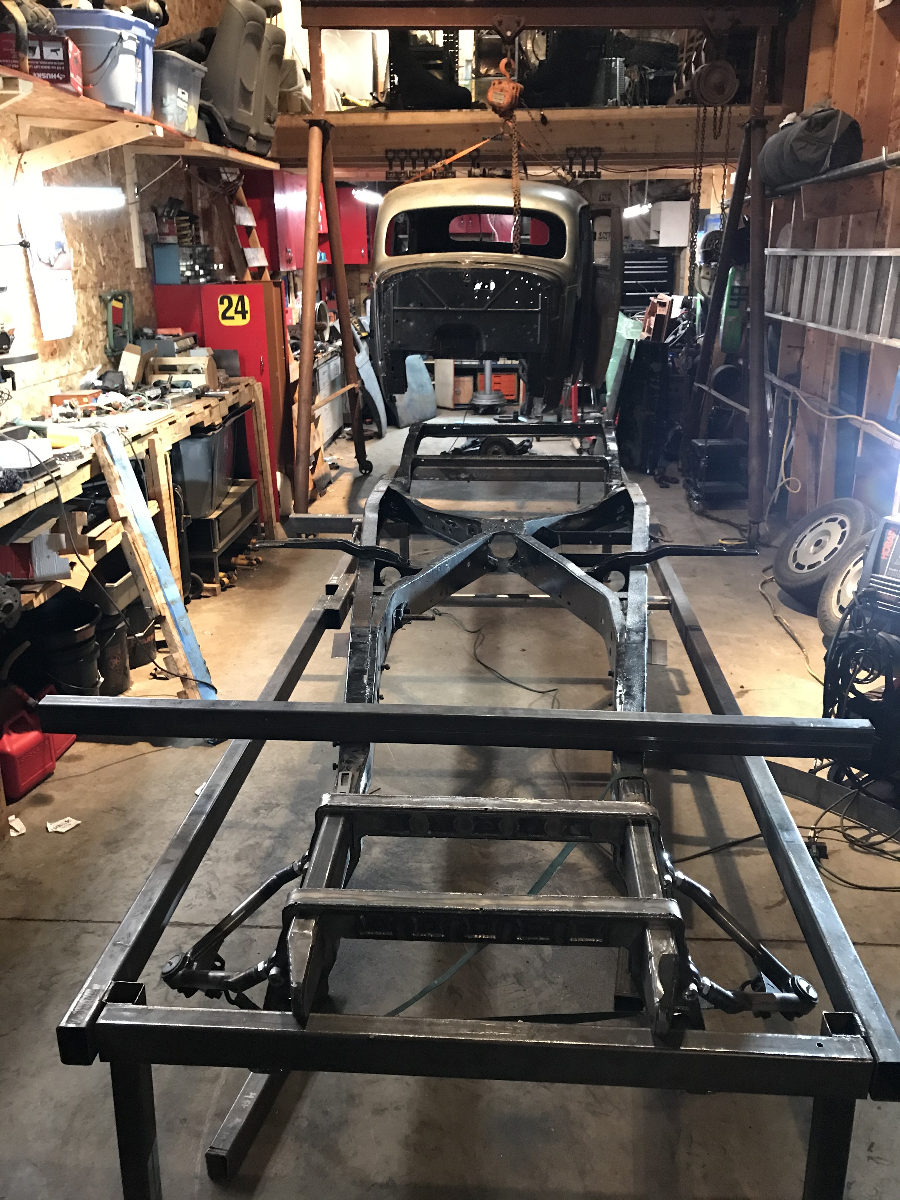
Happy thanksgiving update. This is gonna be a Picture update. Photos might not all be in order.
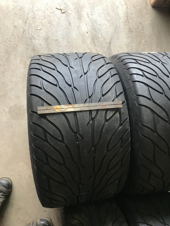
Attachments:
-
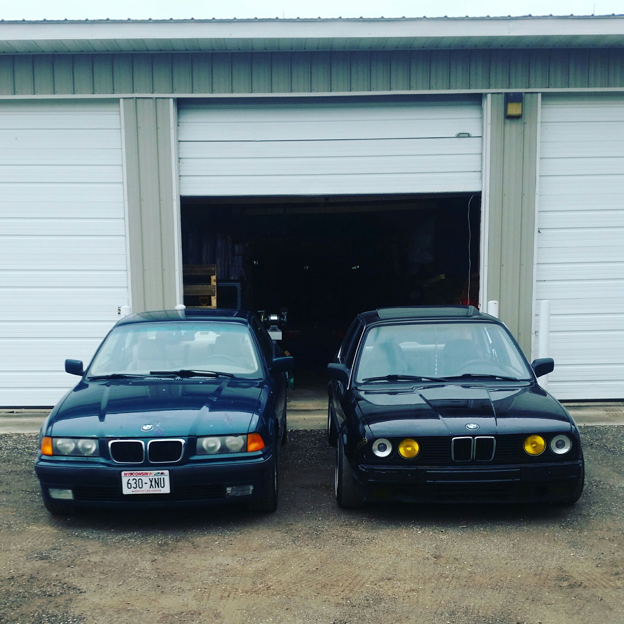
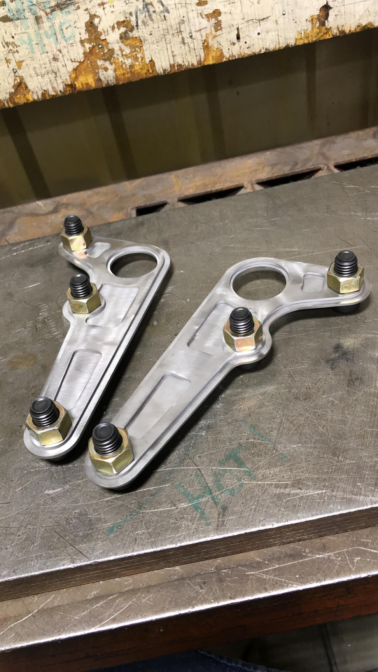
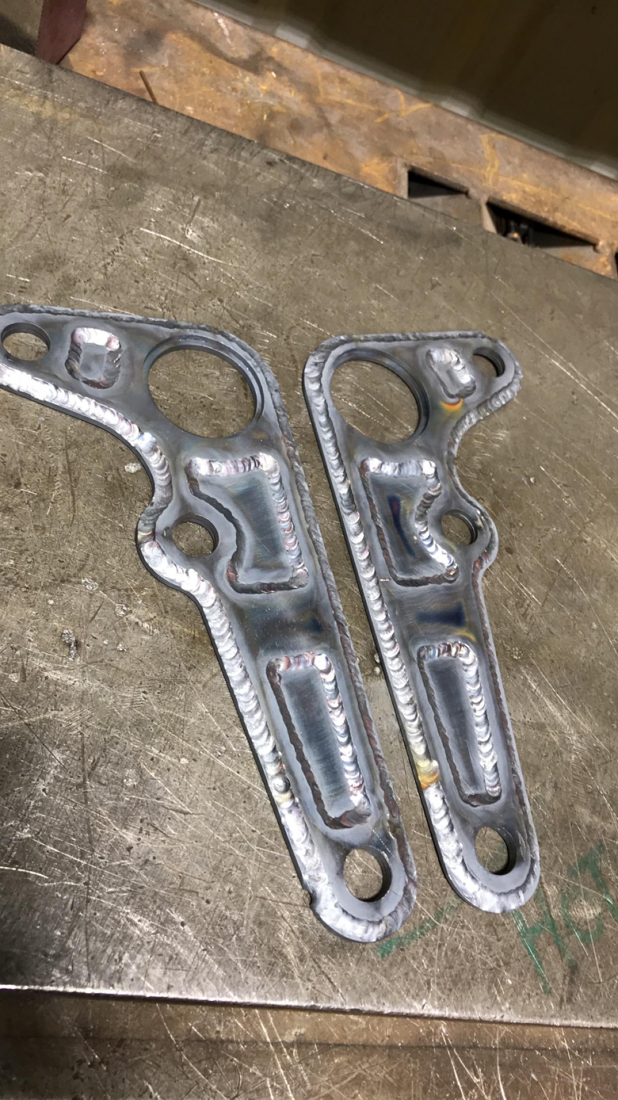
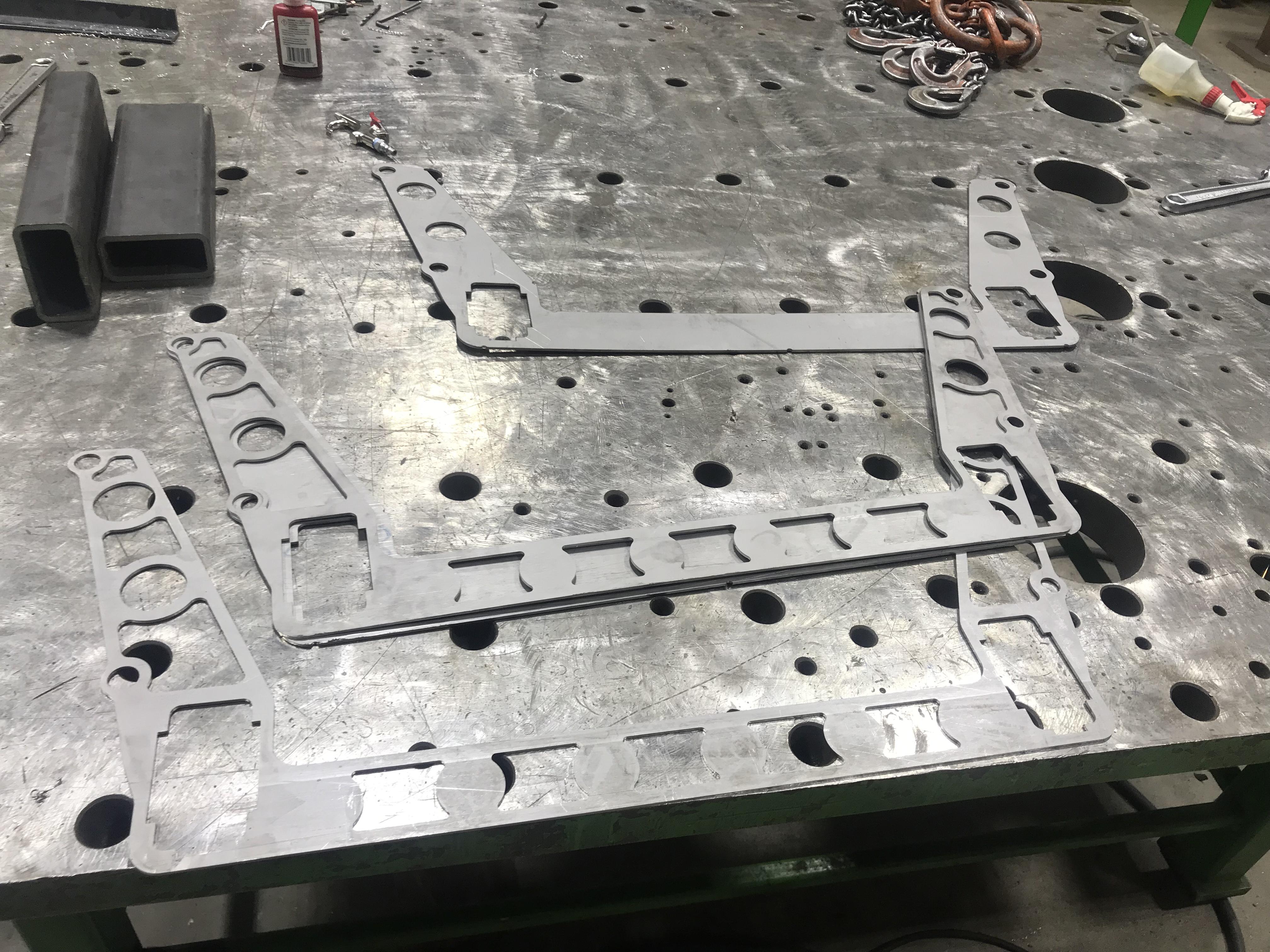
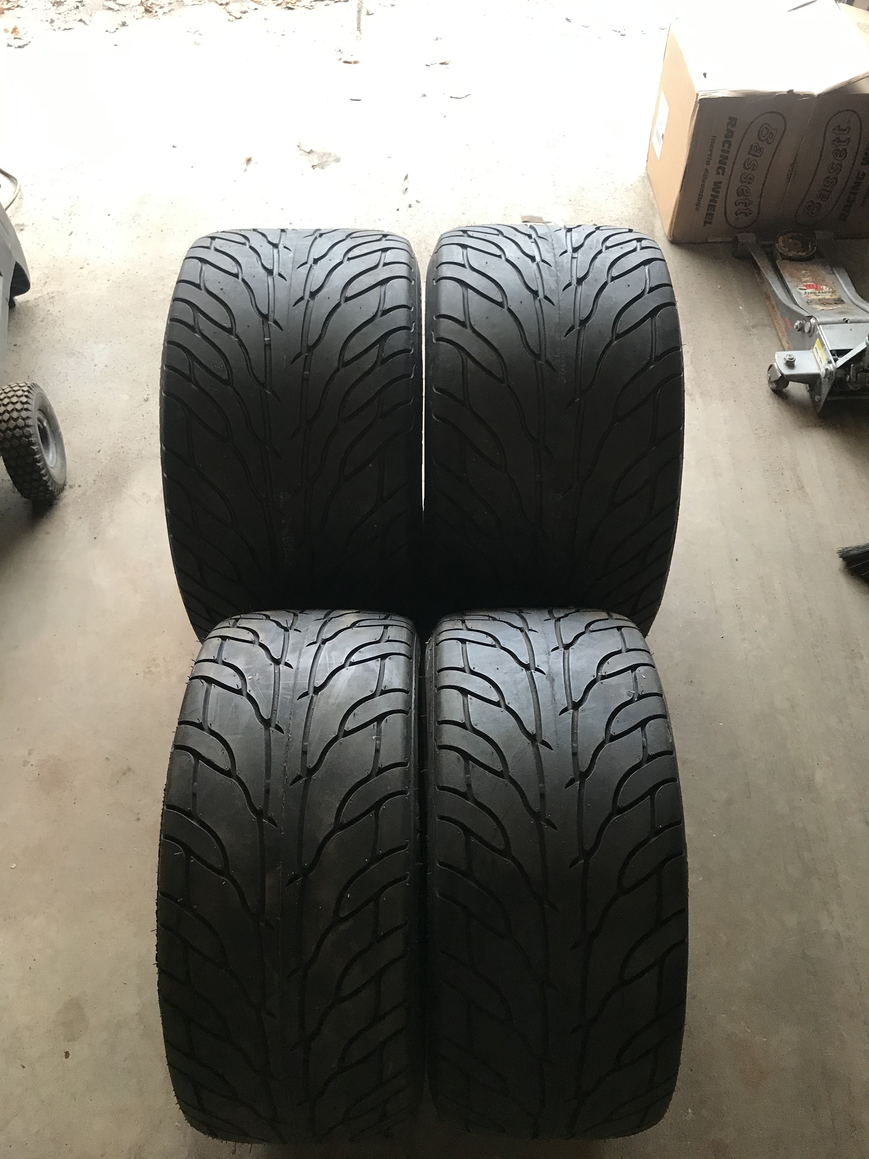
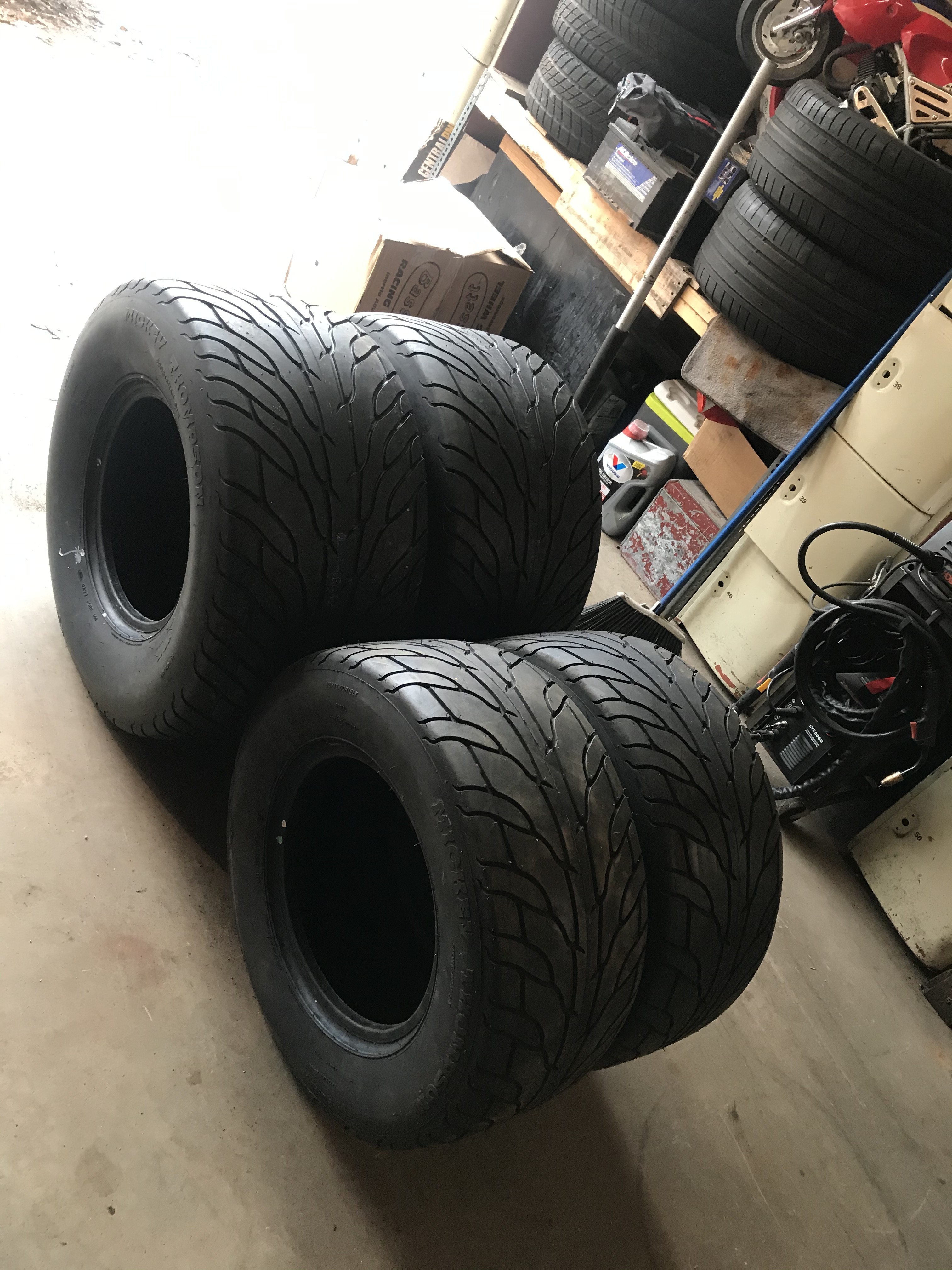
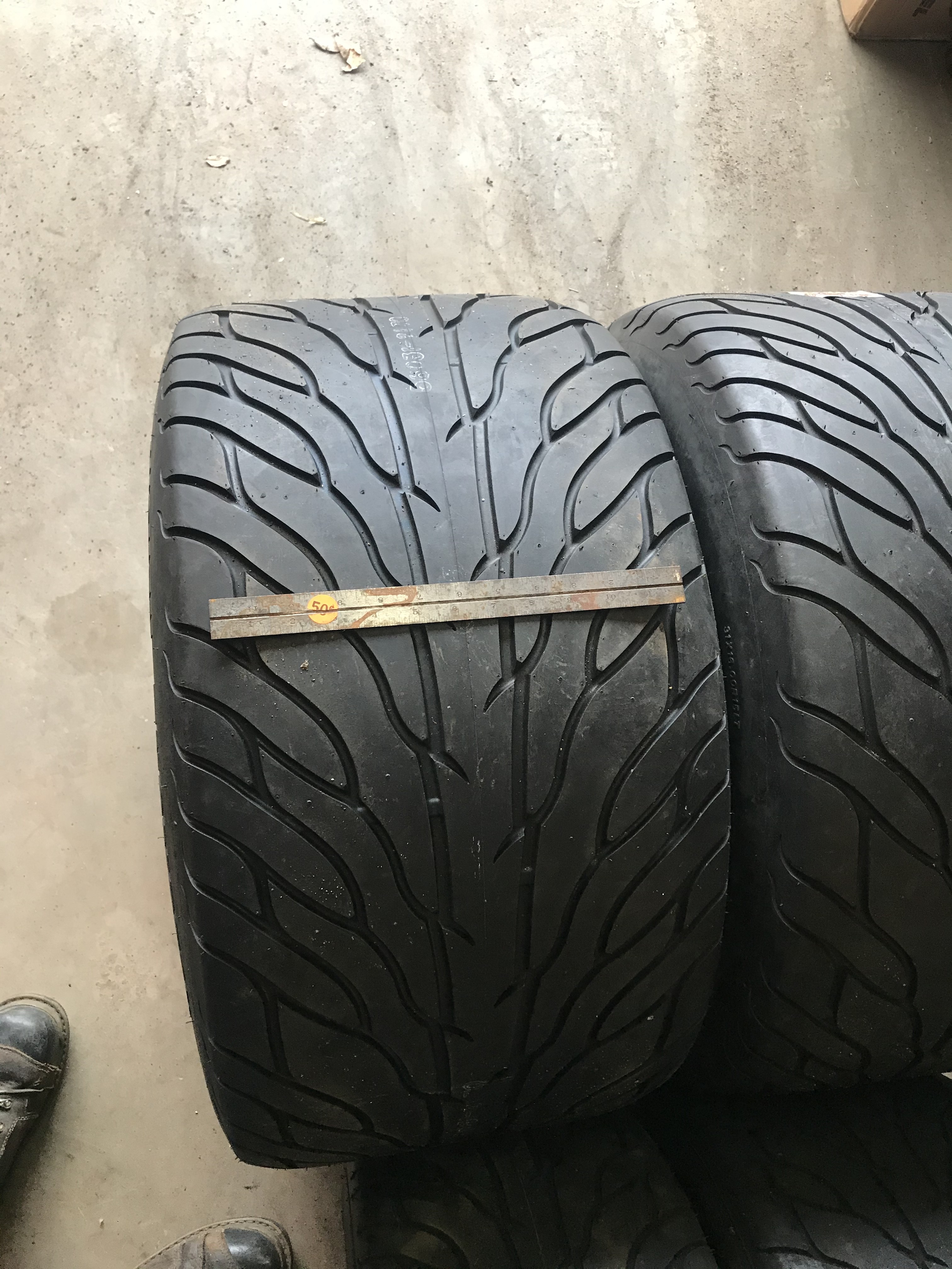
Pulled the frame out from underneath the car and worked on getting the front end mounted to the frame. Holiday week is letting me get some shop time in. I’m just waiting on the rear wheels From basset racing. and then I will have everything to make it a roller. Glad to see all me card board templates and napkin drawings are working out.


Hello! It looks like you're interested in this conversation, but you don't have an account yet.
Getting fed up of having to scroll through the same posts each visit? When you register for an account, you'll always come back to exactly where you were before, and choose to be notified of new replies (either via email, or push notification). You'll also be able to save bookmarks and upvote posts to show your appreciation to other community members.
With your input, this post could be even better 💗
Register Login