
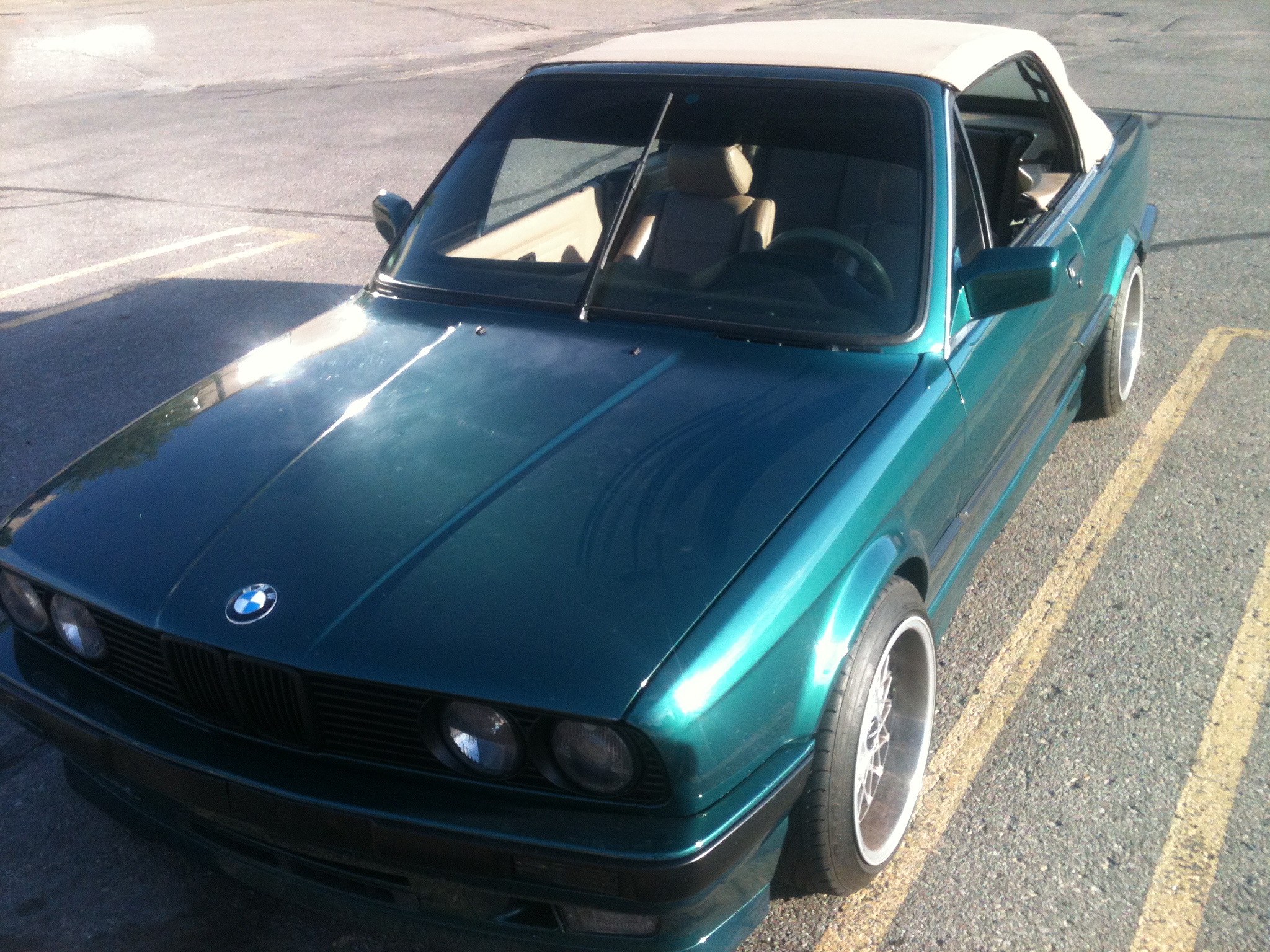
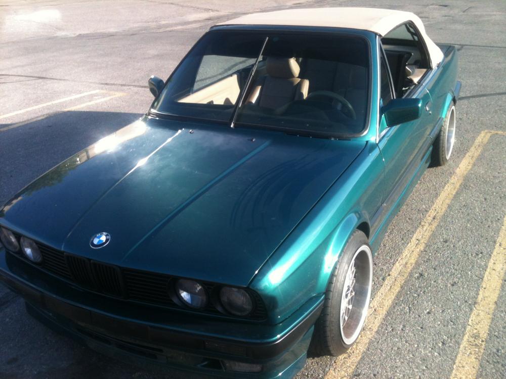
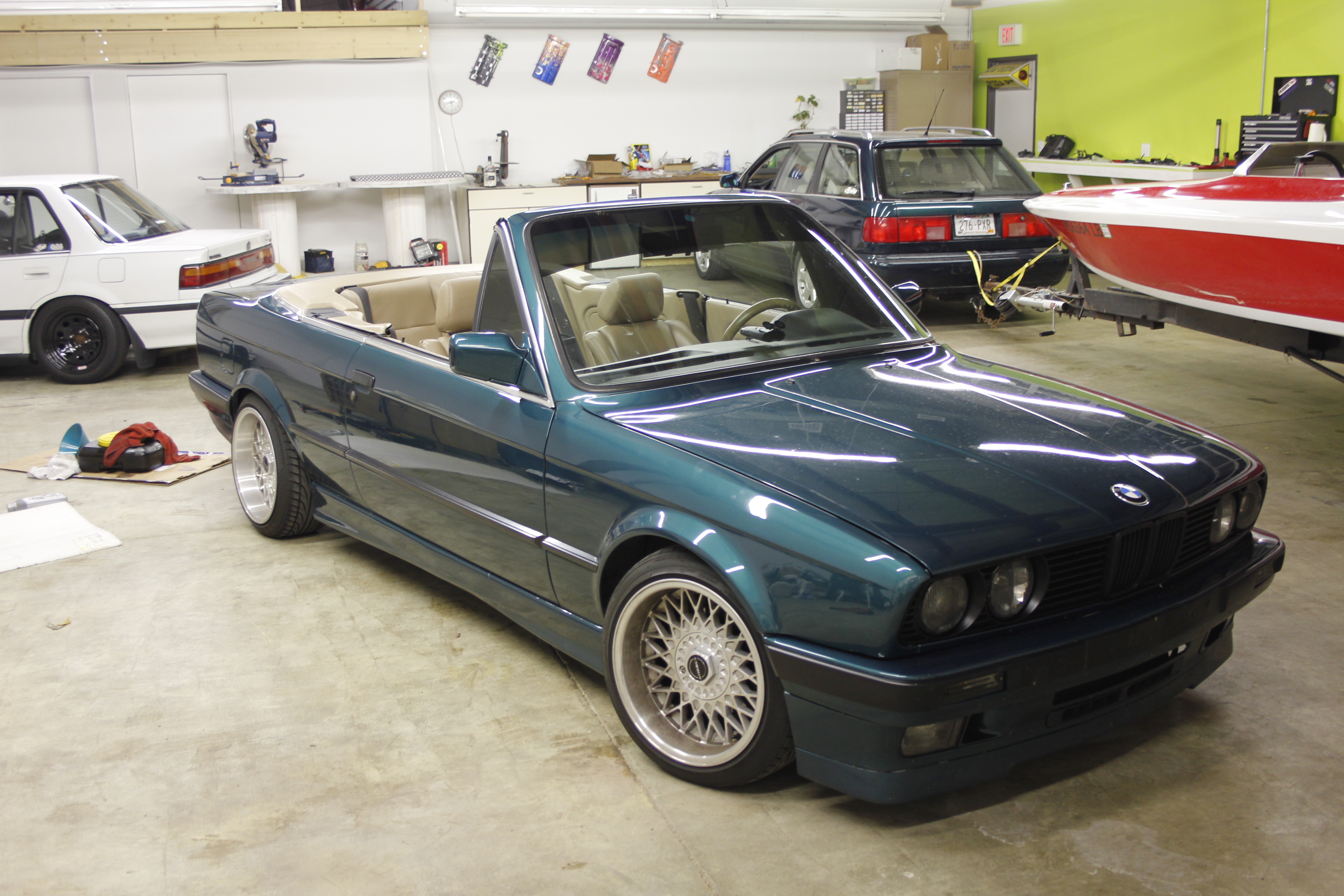
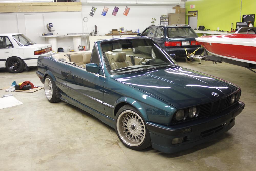
1JZ E30 Vert Build Thread with Pastry filled wheels

-
LOOOOOOOONG overdue update on this car.
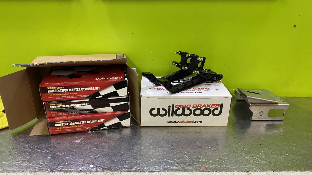
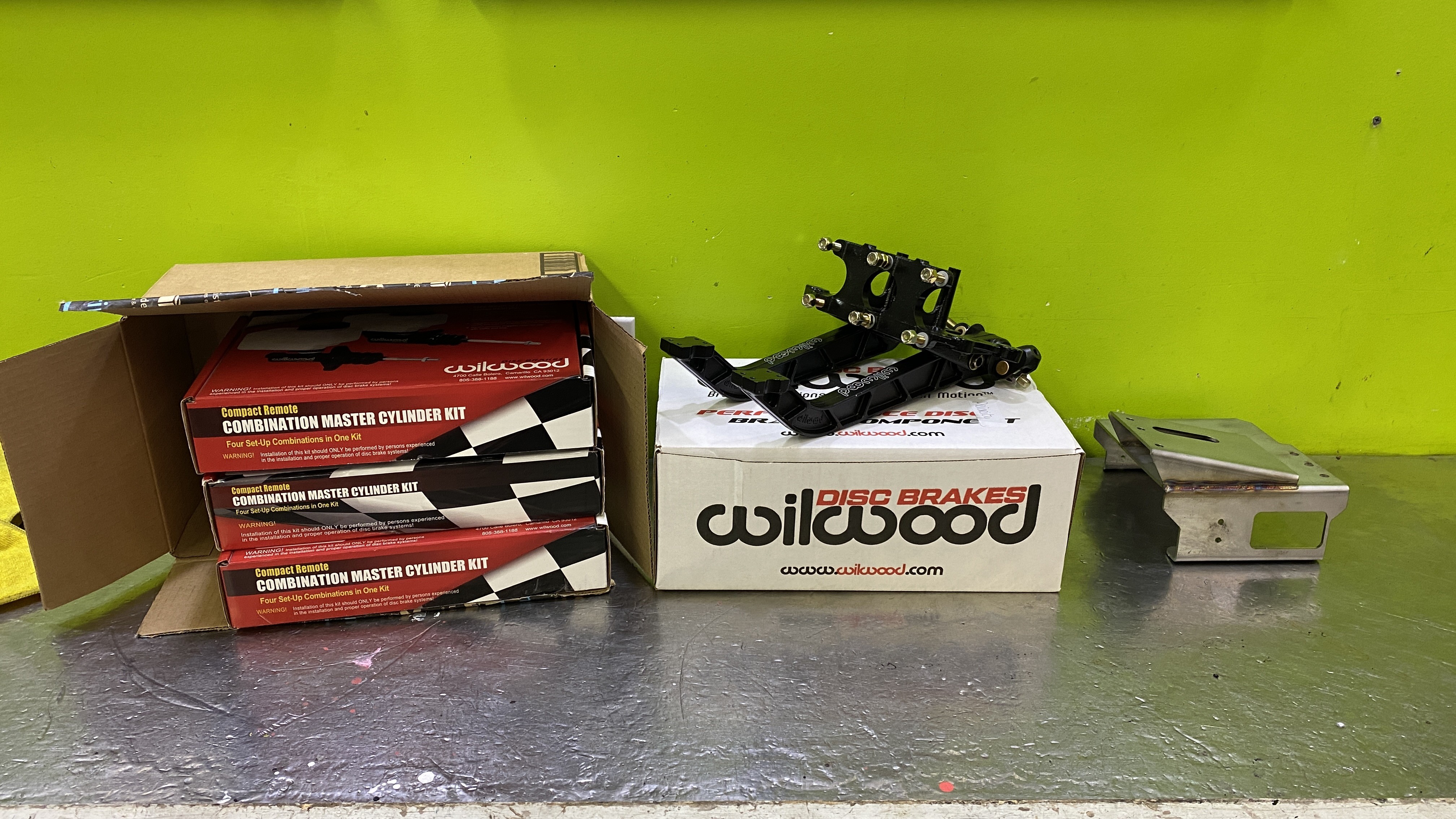
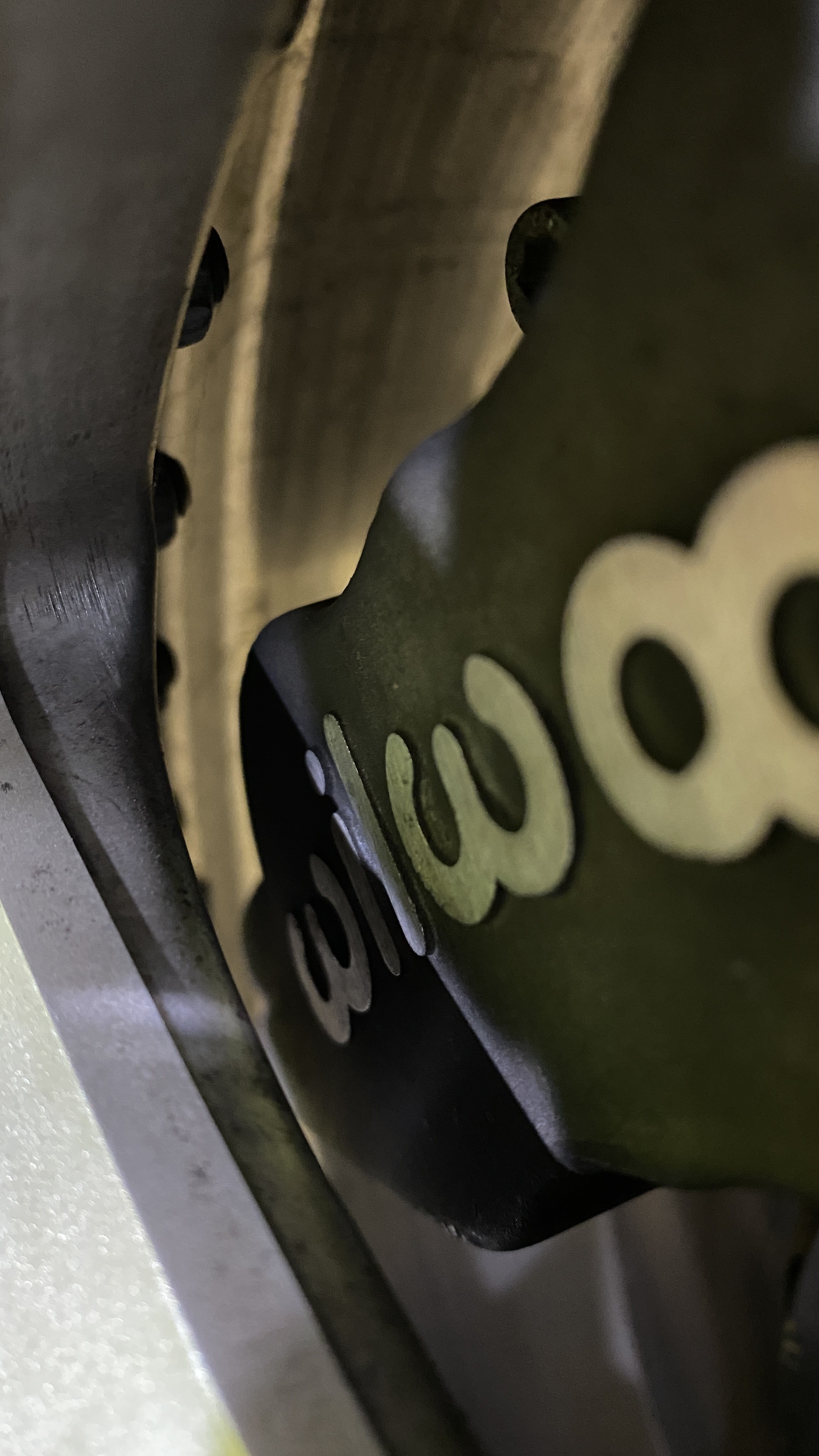
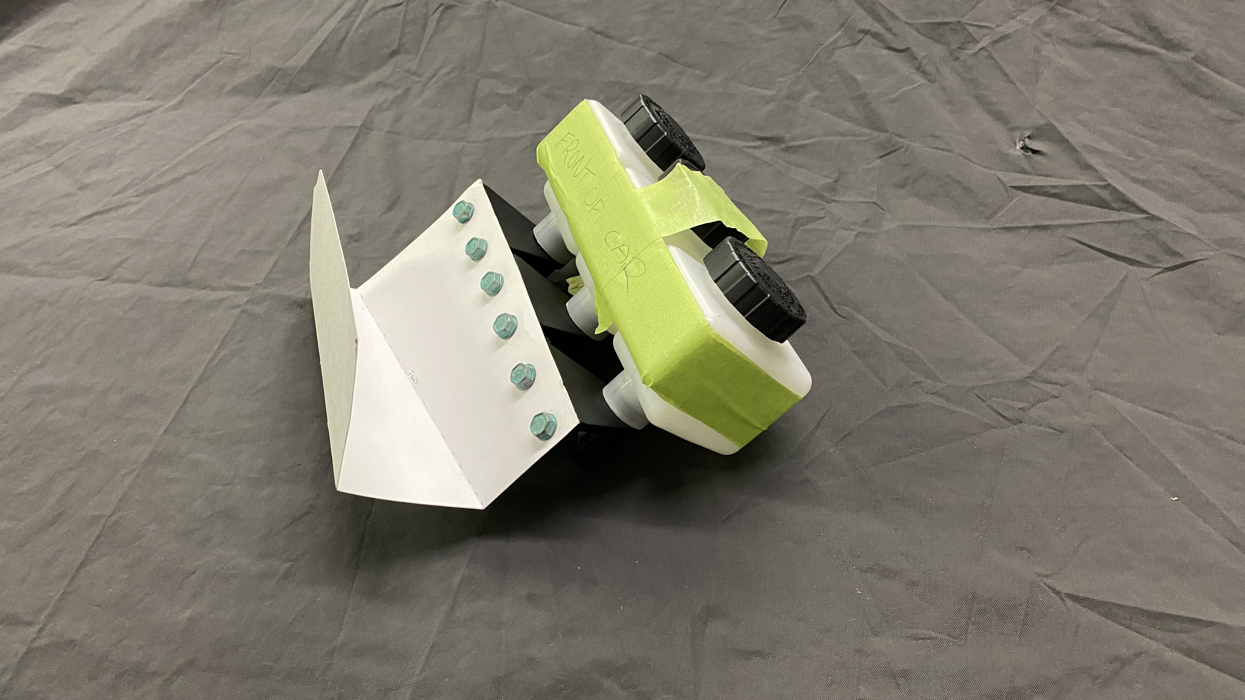
I got all the parts I need to swap the brake system(I think). I called Wilwood and figured out the exact calipers I got from @DrLeadFoot because I needed to get an idea of what size masters I should run with the pedalbox and the calipers front and rear. Despite everything I read on the internet(5/8ths F&R), I wanted to be certain. It turns out, due to the size and stroke if the rear Calipers, Wilwood suggests a 3/4th master for the rear. The front calipers are an older design (cast with raised Wilwood logo) which I actually prefer but still utilize the same parts as the new design (cast with printed logo) and wilwood said a 5/8ths is perfect for them.
So here is what I ended up getting;
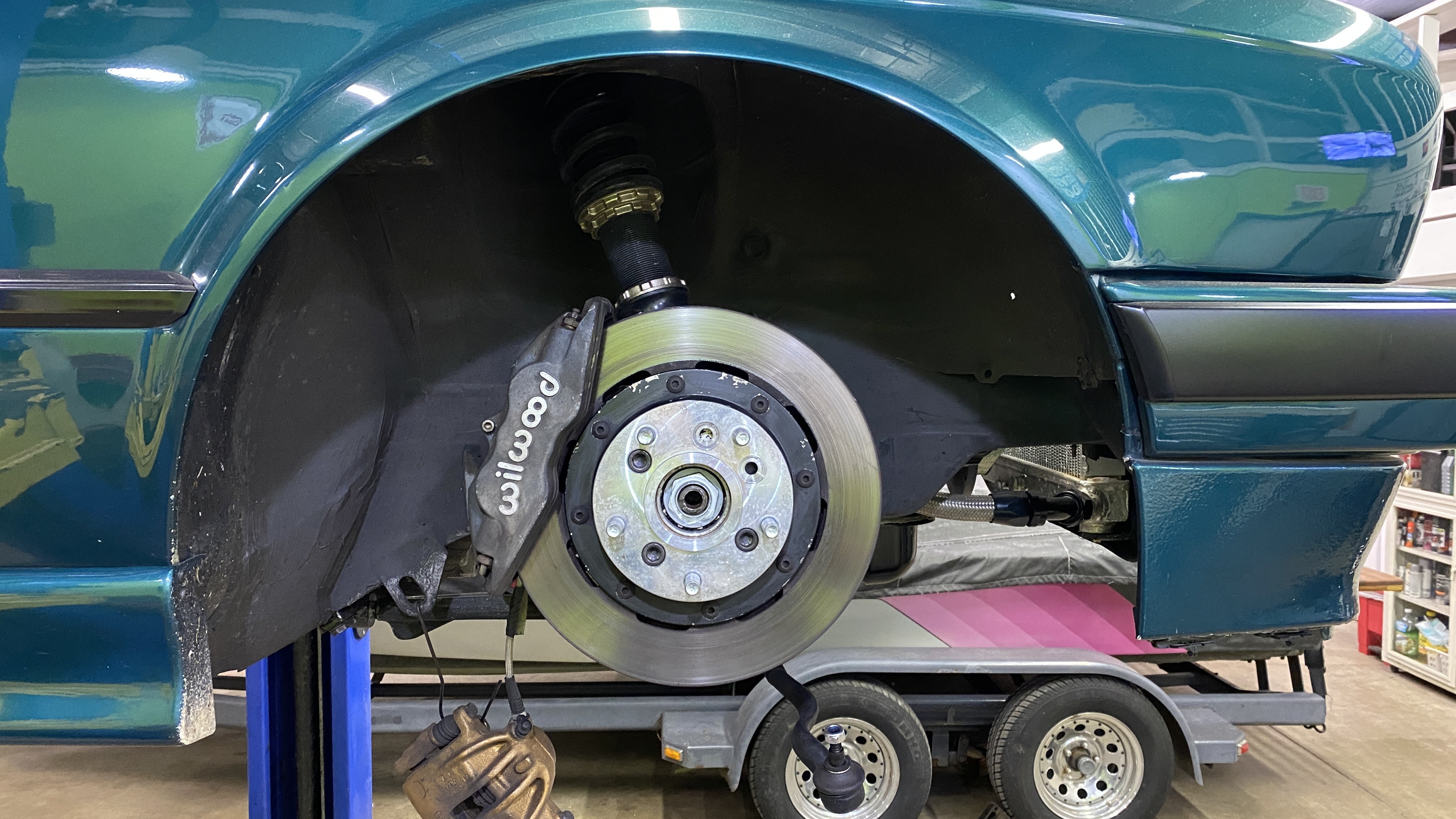
- Wilwood 4 piston Forged Superlites
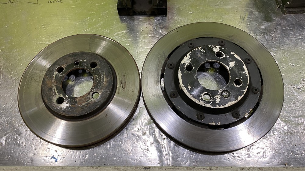
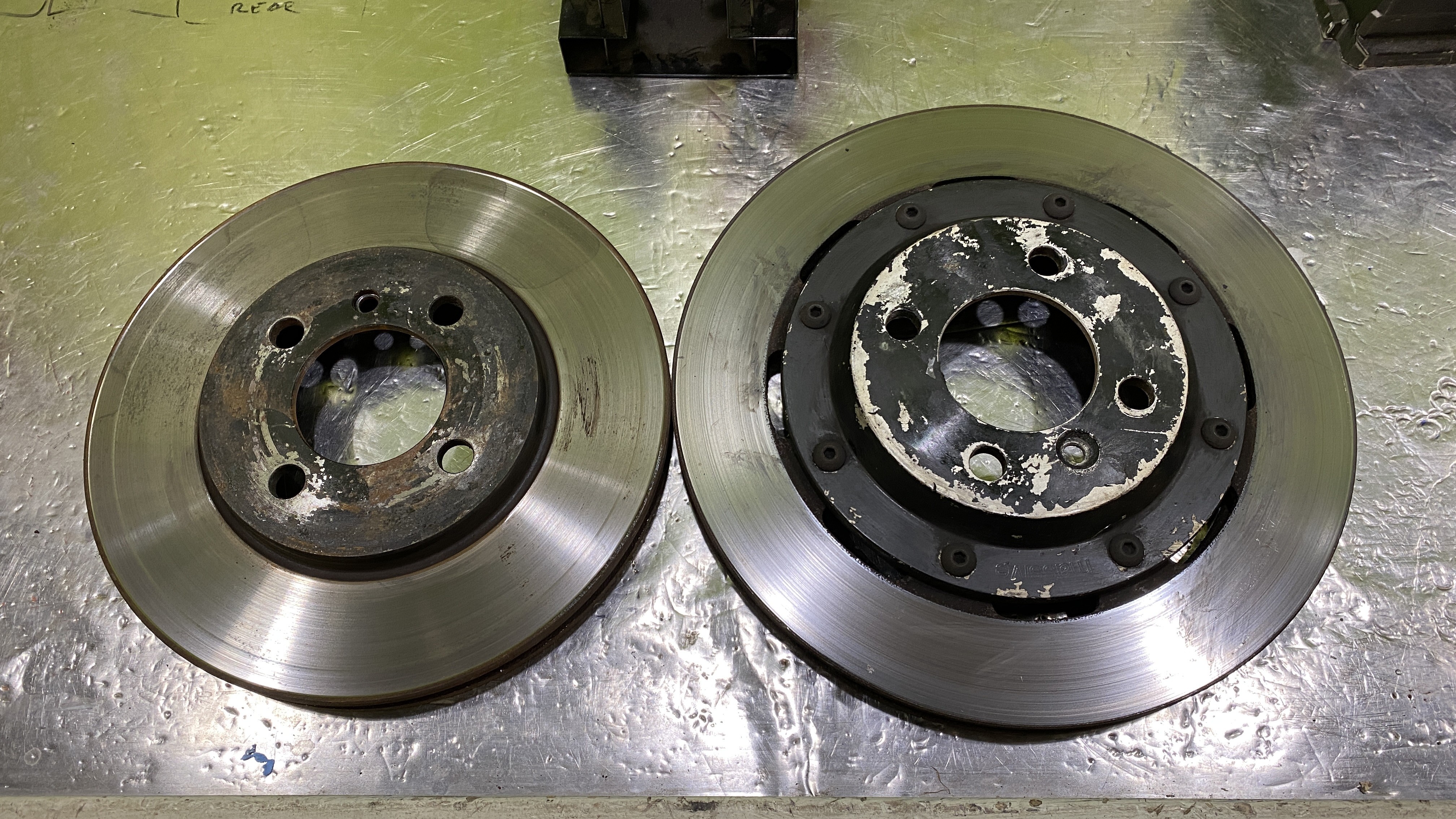
- Wilwood 11.75" Ultralite 2 pc rotors
- Wilwood BP-20 pads
- Wilwood 340-11299 pedal assembly
- Wilwood 5/8th master for the front
- Wilwood 3/4th master for the rear
- Wilwood 3/4th master for the clutch
- Garagistic mounting bracket
- Wilwood bias valve
Size comparison of the rotors
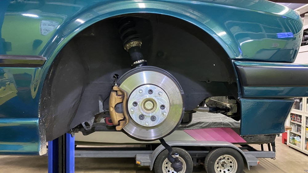
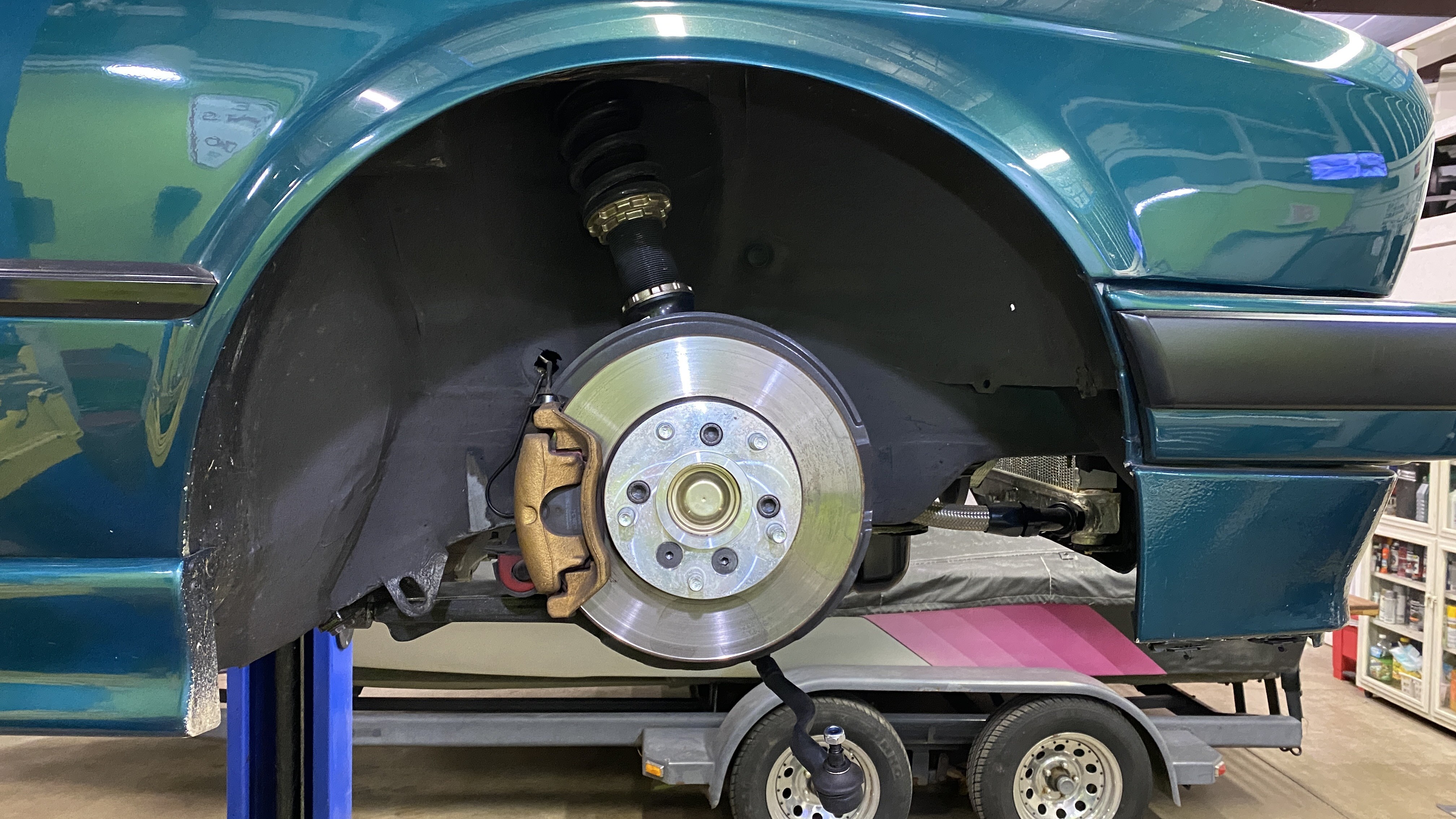
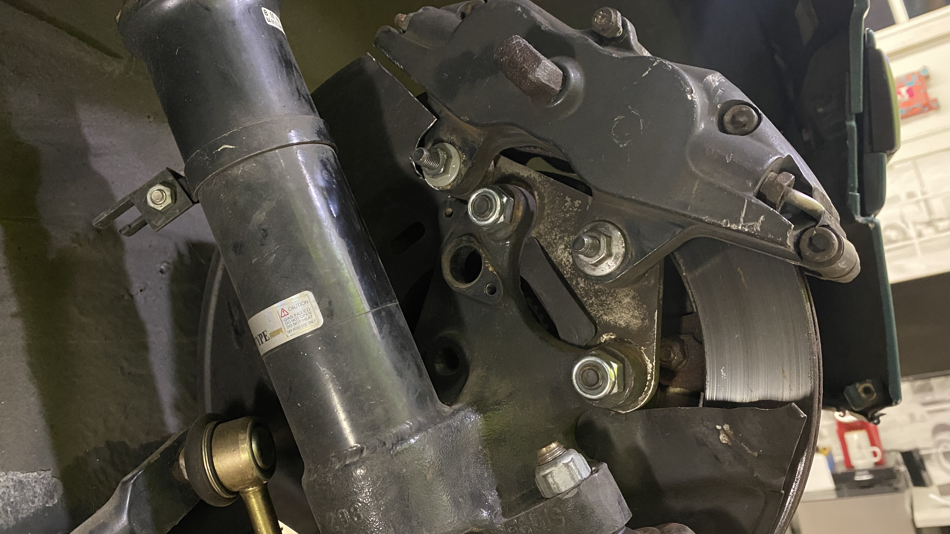
The old brake setup
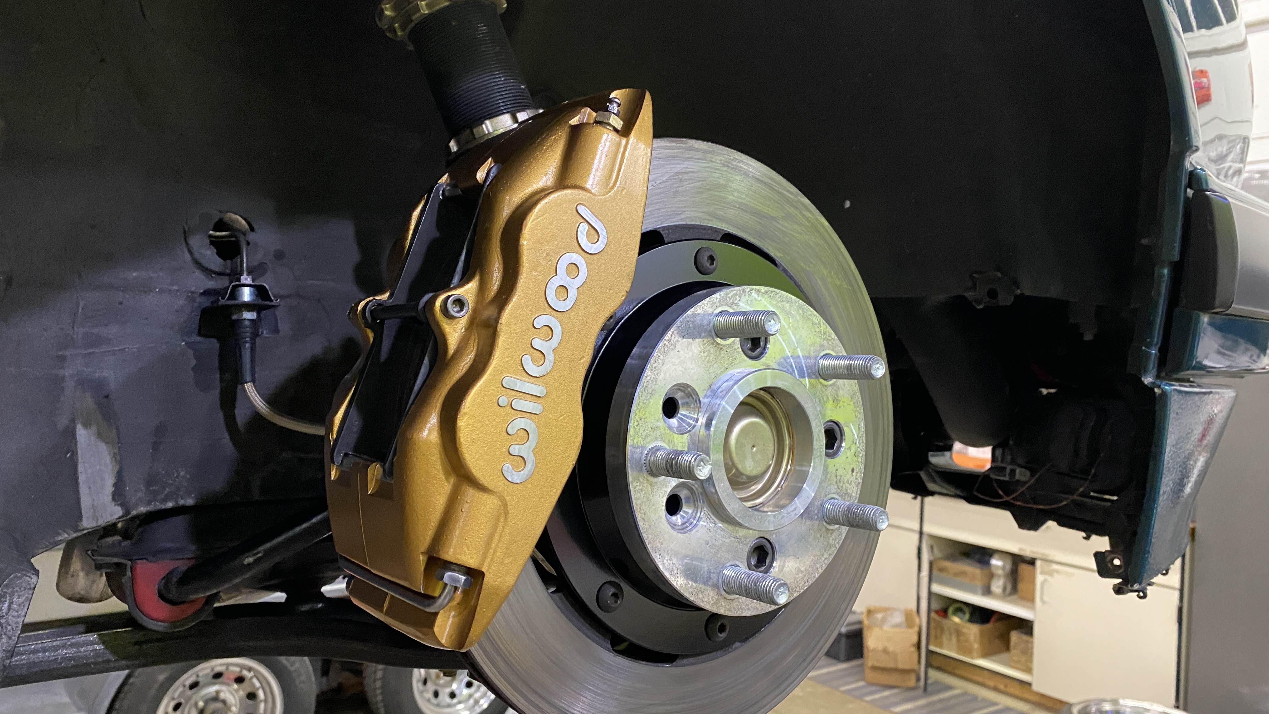
The new brake setup
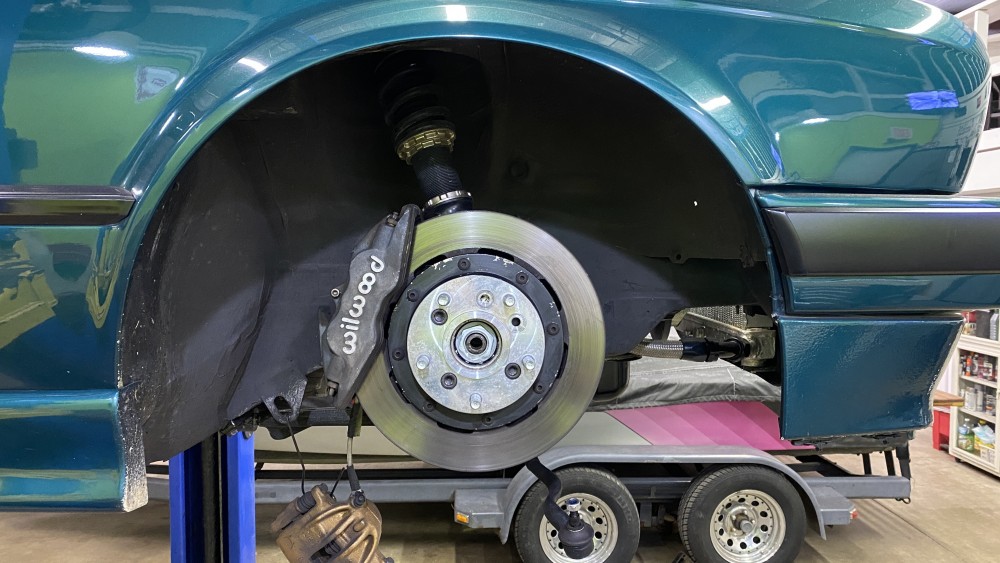
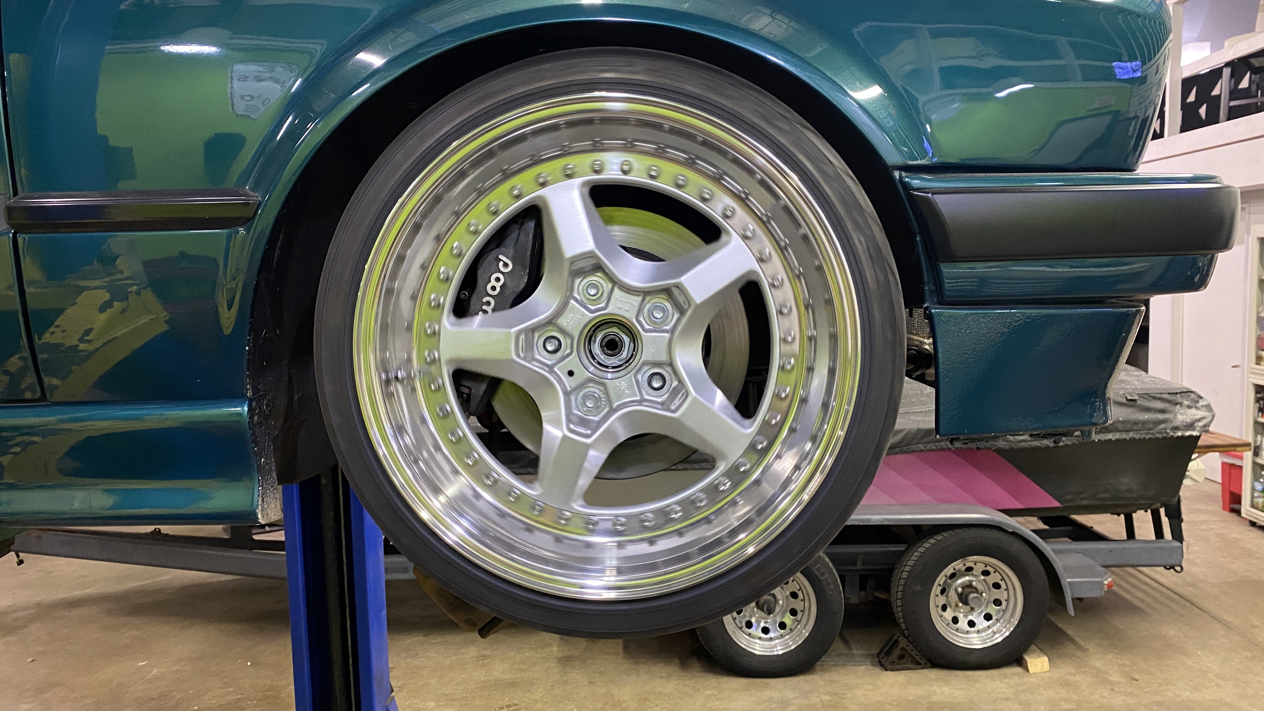
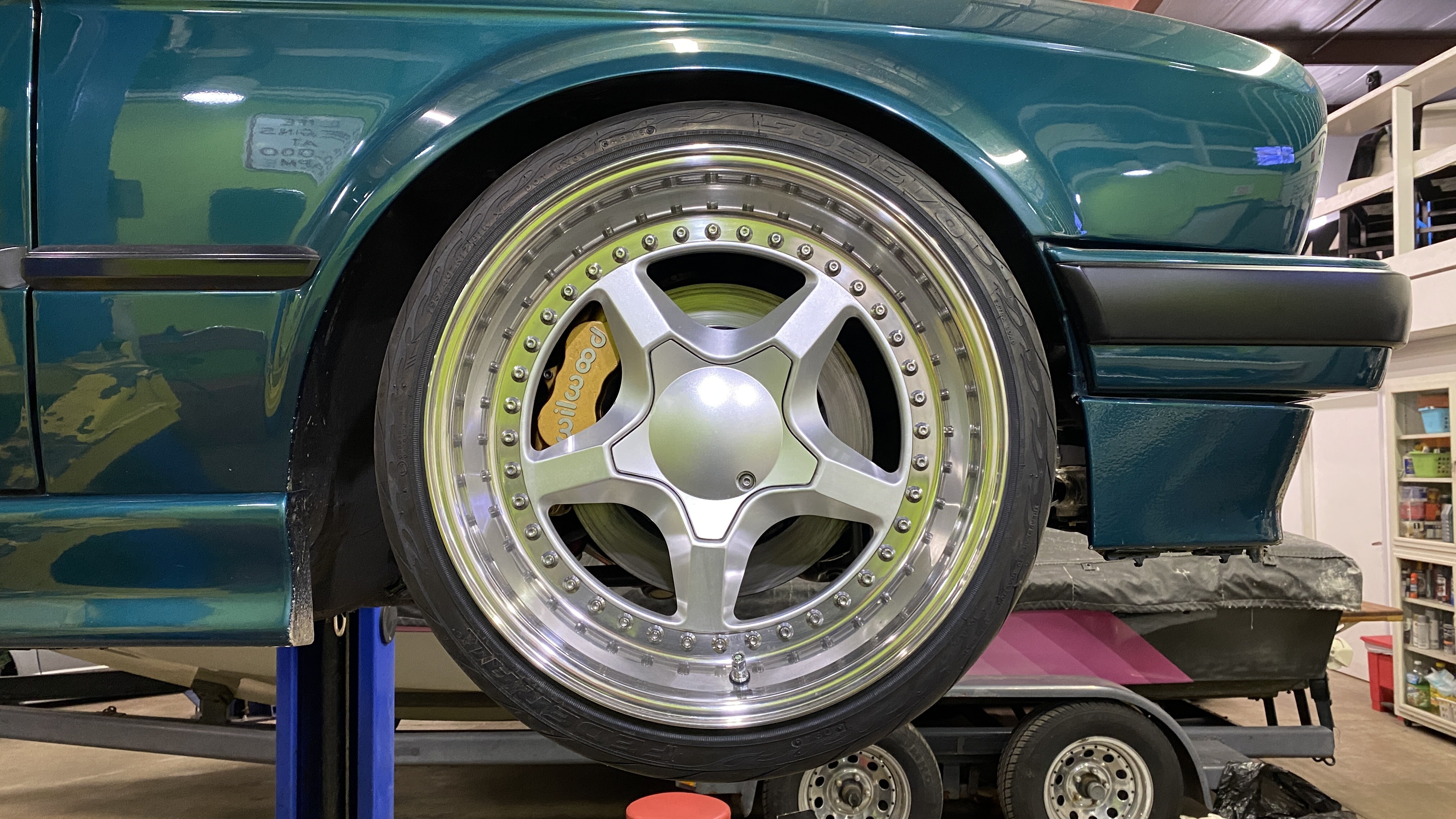
And a test fit with my wheels
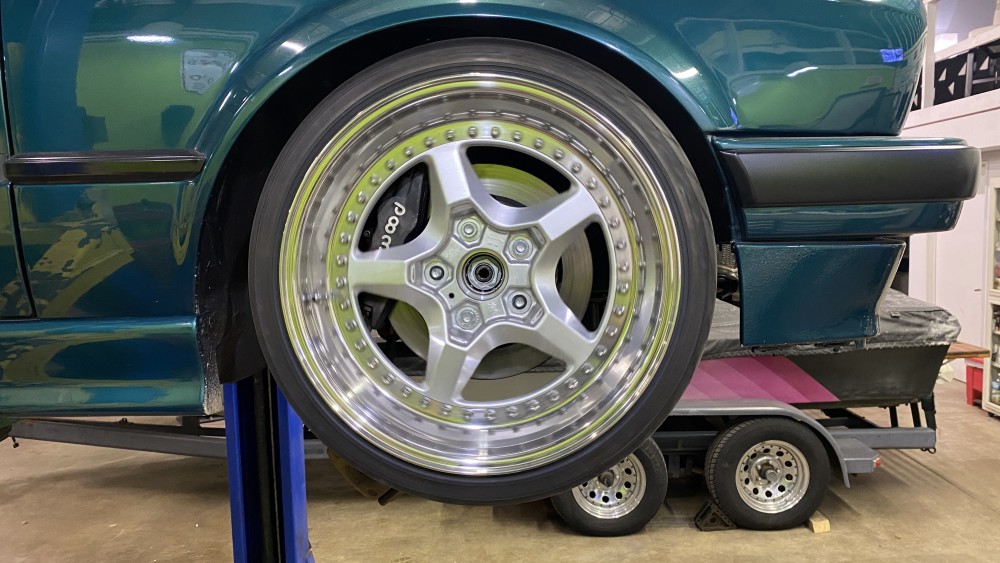
Super stoked that these fit with ample room left
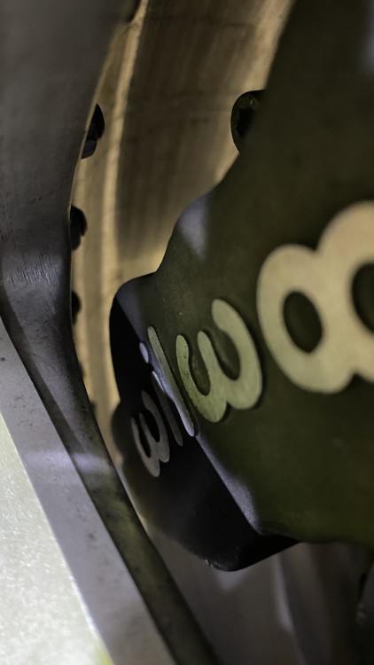
It took me about a good 3 hours to fit everything and trim the heat shields and find hardware that would work for mocking up.
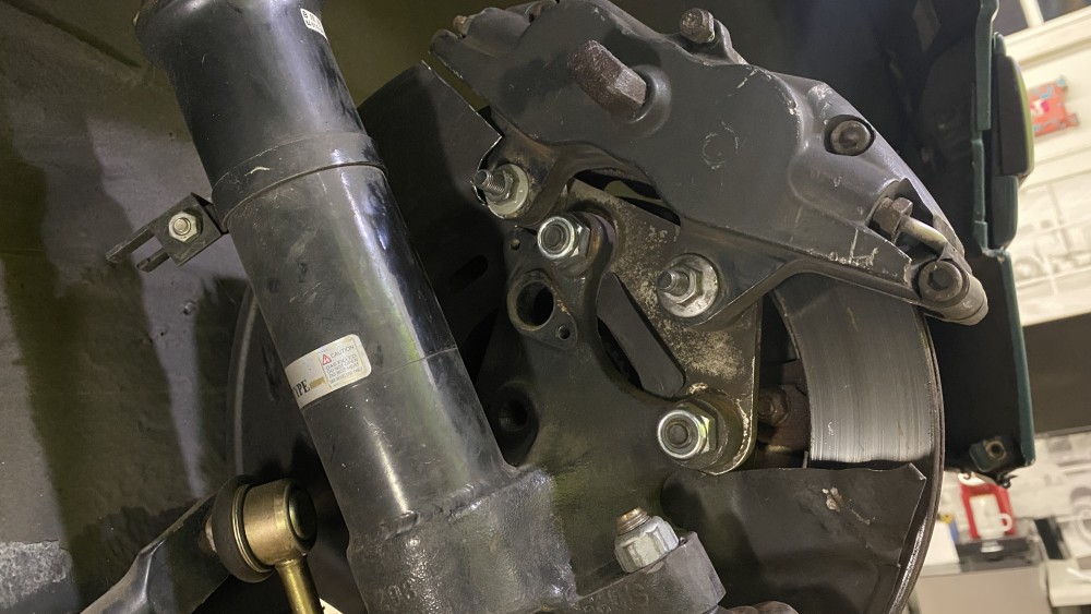
As of now I only have the rotors and calipers installed just to mock them up. They will be coming back off and the new rotors will go on, the hats and calipers will be painted and rebuilt before finally assembly.
The next steps now is to get the pedal box to fit in the car. It says on the garagistic site that I need a non-airbag steering column, which I am going to soon learn the reason behind.

https://www.instagram.com/_jdesigner_/ http://nevertoolow.tumblr.com/
🥳SOLD BMW E24 633CSI - BMW M30B32 🧪SOLD HCH ES9 - 1.3 LDA
👽BMW E30 325IC - Toyota 1JZ-GTE ⏰ HONDA EF9 CIVIC SI - JDM B18C5
☠️BMW E36 318i - Ford 5.0 FE302 🚴♂️ GT-Labomba - 26x2.75 Freeride
🤹♀️SOLD BMW E36/7 Z3 - BMW M54B25 🧓SOLD BMW E10 2002 - BMW M10M05 -
@johnprusinski might have some tips, I remember he had some choice words about that garagistic setup.
-
@johnprusinski might have some tips, I remember he had some choice words about that garagistic setup.
He already mentioned to me that it’s a huge PITA.
https://www.instagram.com/_jdesigner_/ http://nevertoolow.tumblr.com/
🥳SOLD BMW E24 633CSI - BMW M30B32 🧪SOLD HCH ES9 - 1.3 LDA
👽BMW E30 325IC - Toyota 1JZ-GTE ⏰ HONDA EF9 CIVIC SI - JDM B18C5
☠️BMW E36 318i - Ford 5.0 FE302 🚴♂️ GT-Labomba - 26x2.75 Freeride
🤹♀️SOLD BMW E36/7 Z3 - BMW M54B25 🧓SOLD BMW E10 2002 - BMW M10M05 -
Calipers are all painted and I cleaned up the hardware. I was going to get new pad guides instead of cleaning them but they were $80 and I realized I was just being lazy.
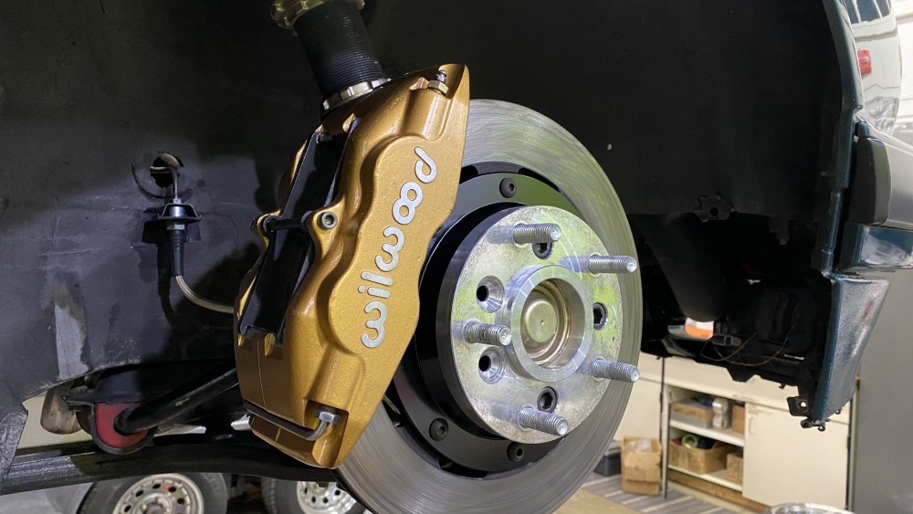
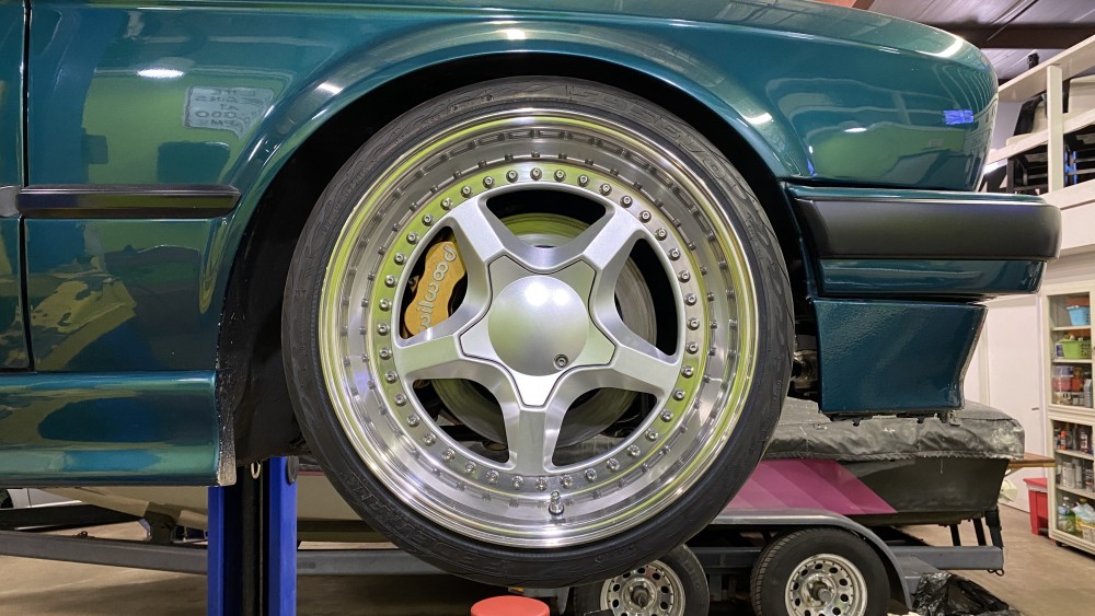
I have yet to start digging under the dash, that’s next.
https://www.instagram.com/_jdesigner_/ http://nevertoolow.tumblr.com/
🥳SOLD BMW E24 633CSI - BMW M30B32 🧪SOLD HCH ES9 - 1.3 LDA
👽BMW E30 325IC - Toyota 1JZ-GTE ⏰ HONDA EF9 CIVIC SI - JDM B18C5
☠️BMW E36 318i - Ford 5.0 FE302 🚴♂️ GT-Labomba - 26x2.75 Freeride
🤹♀️SOLD BMW E36/7 Z3 - BMW M54B25 🧓SOLD BMW E10 2002 - BMW M10M05 -
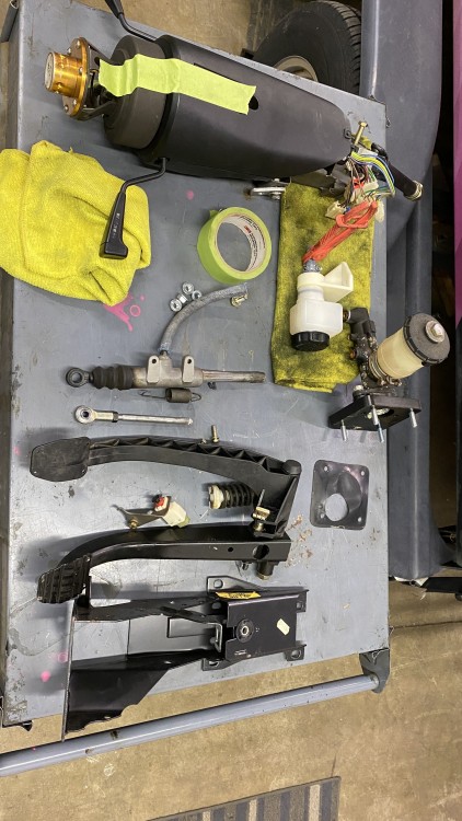
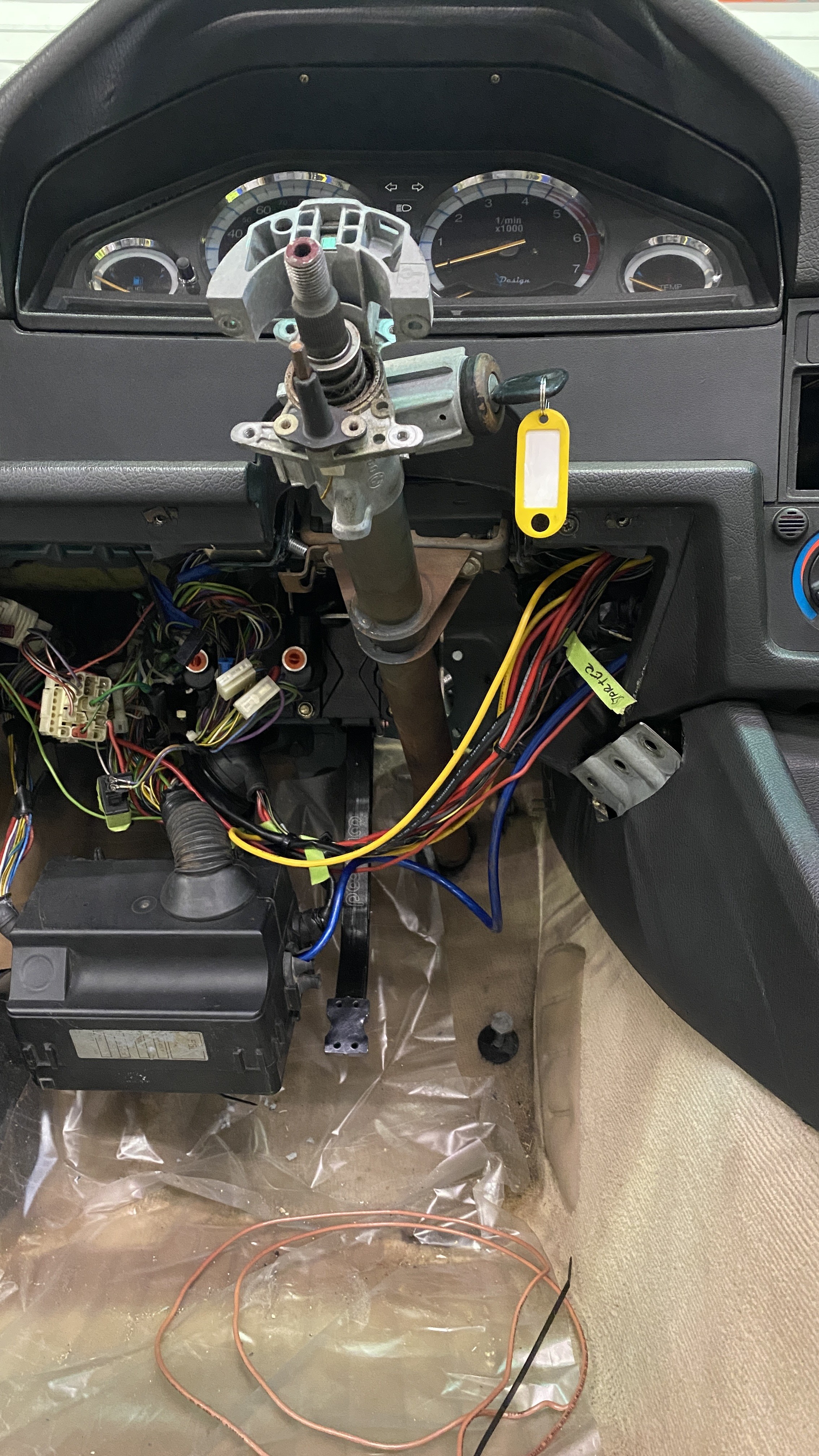
I started on the more frustrating part of the brake upgrade. So far I haven’t determined that I can use my airbag column per garagistics instructions. But they also said I need to remove my dash, and I proved that was a lie already.
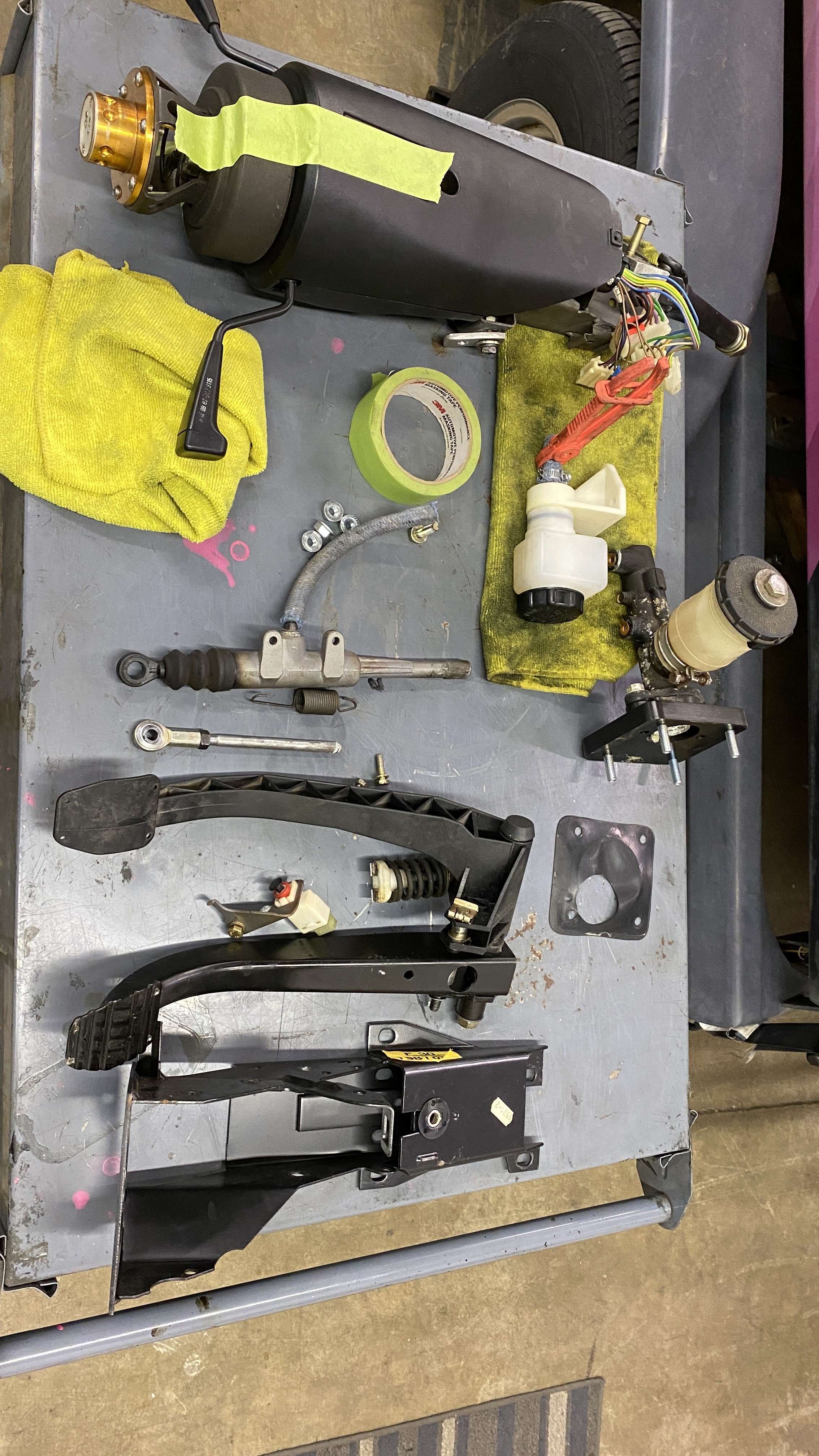
Here is all the factory parts out of the car..
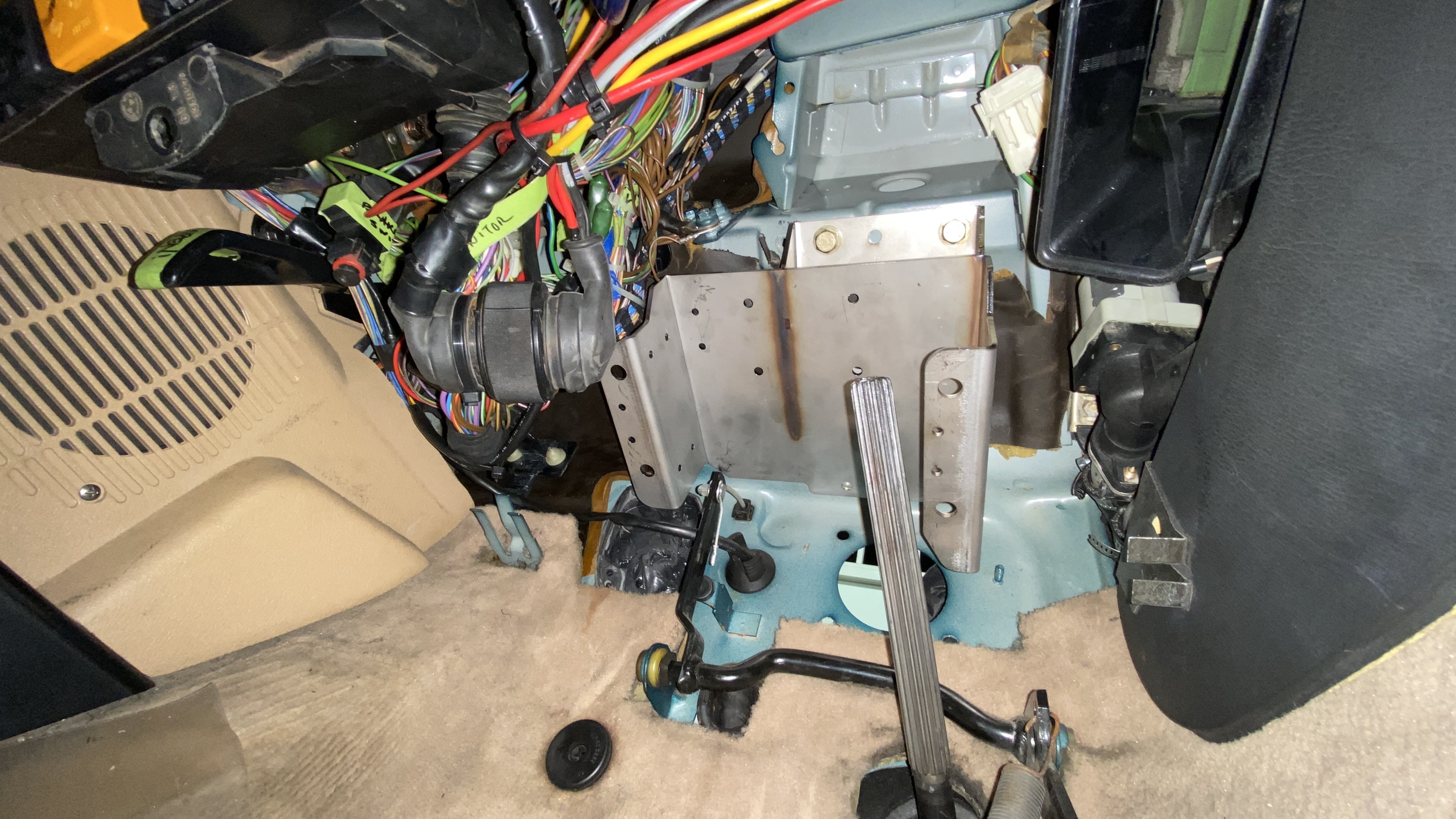
This is a shot of the garagistic bracket mocked up before I drill the holes in the firewall. I later noticed before I drilled the holes that I was off by 1 bolt and had to shift the whole thing to the left. I’m glad I noticed before drilling.
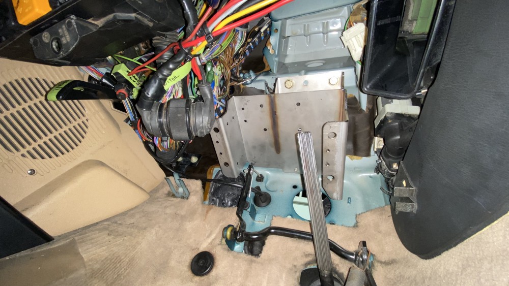
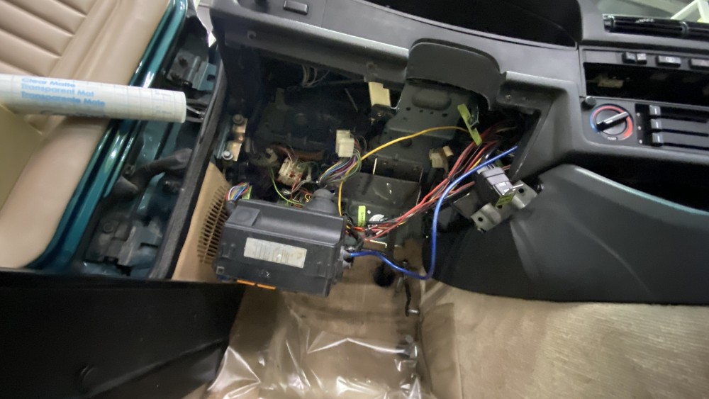
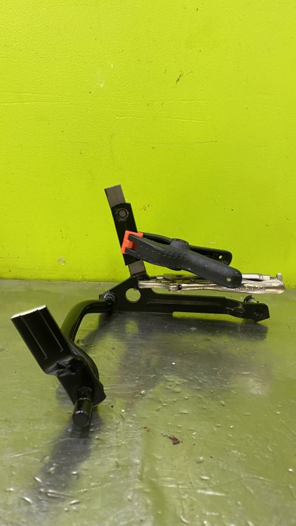
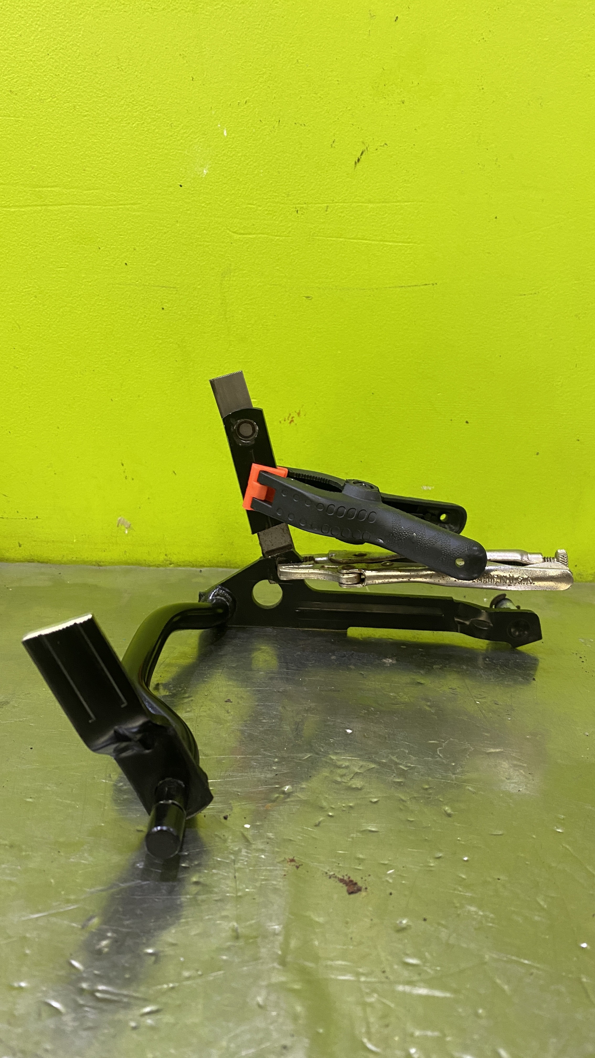
I also have to modify the throttle lever. Originally the throttle cable exits far to the left of the pedal assembly. I had to cut the cam portion of the lever as it hits the clutch pedal if you don’t. I plan on welding it above the pivot of the pedal itself. That’s what you can see mocked up here. What’s nice about this is that the cable will now exit right behind the manifold and give it a cleaner look.
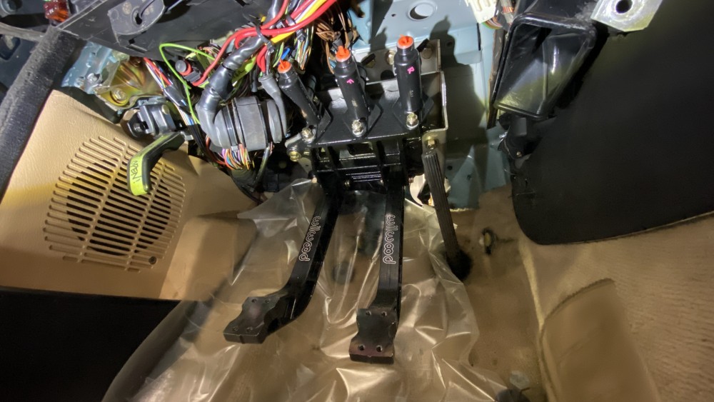
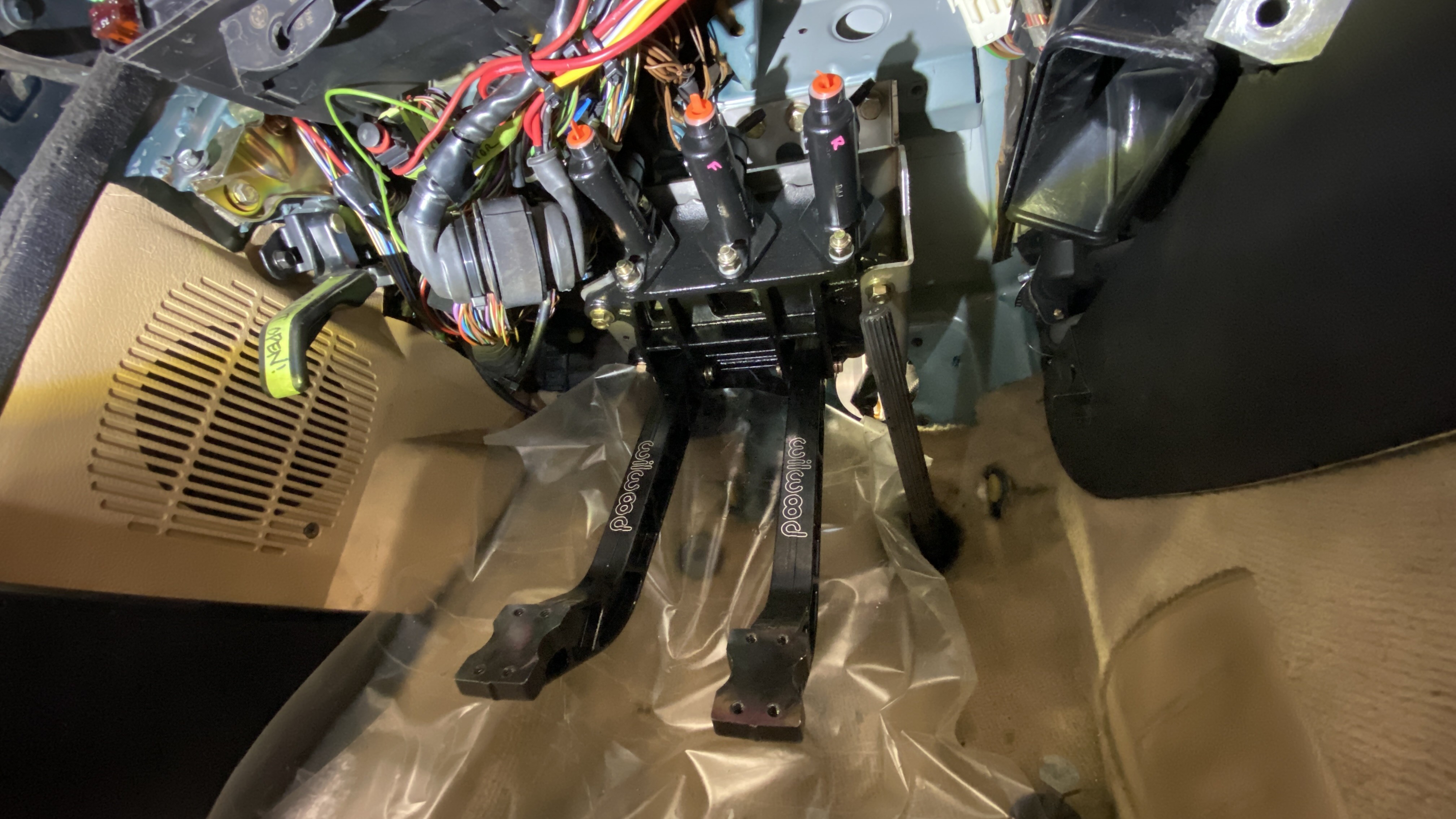
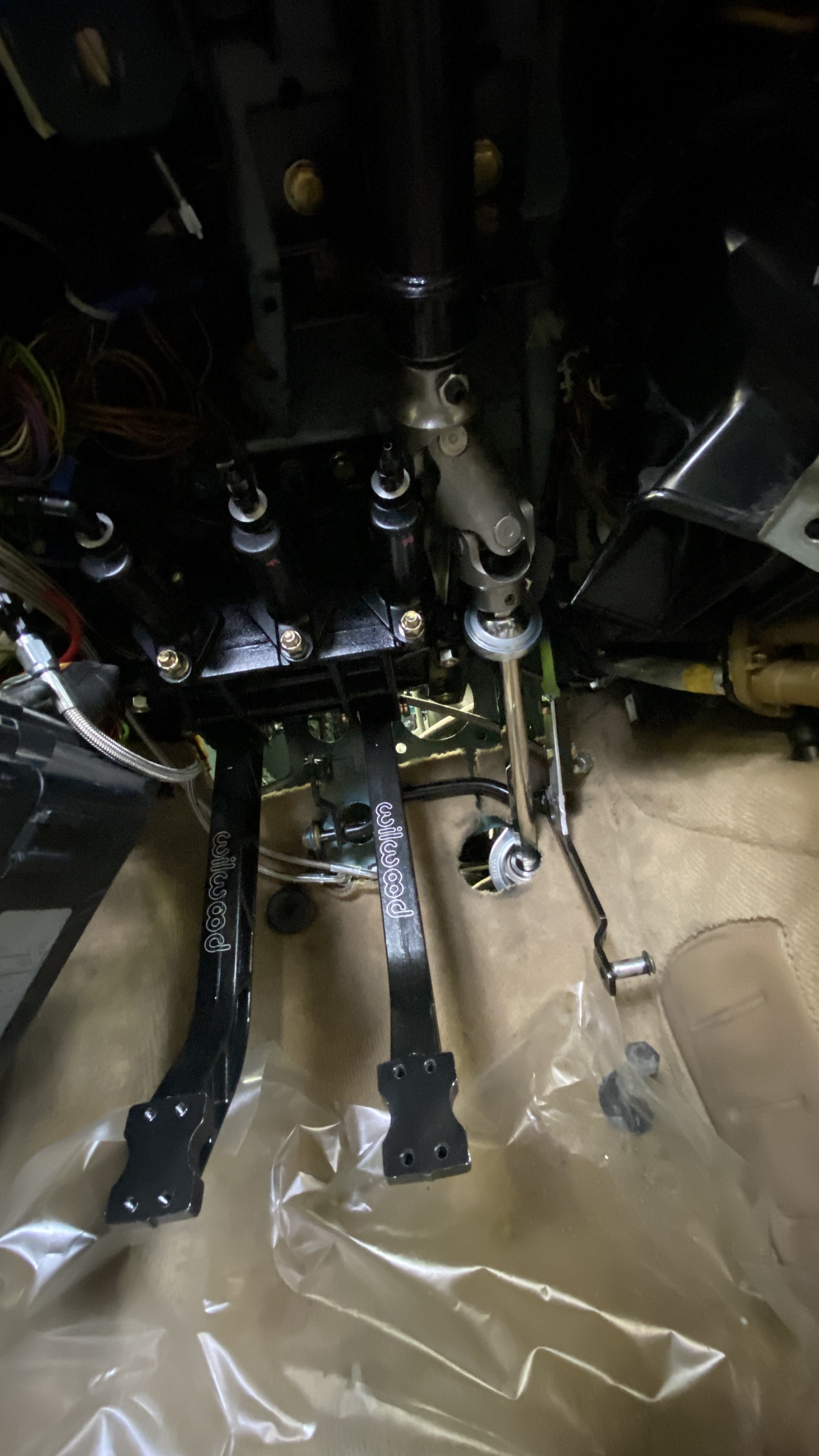
The pedals in their final resting place. Unfortunately they will probably come back out a few more times as I route the brake lines and reservoir lines.
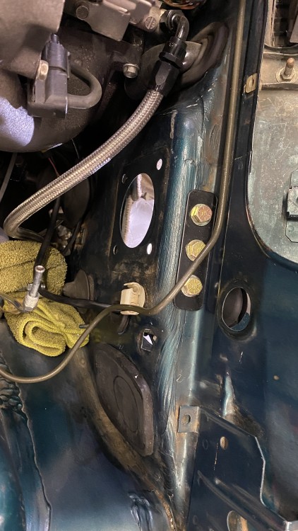
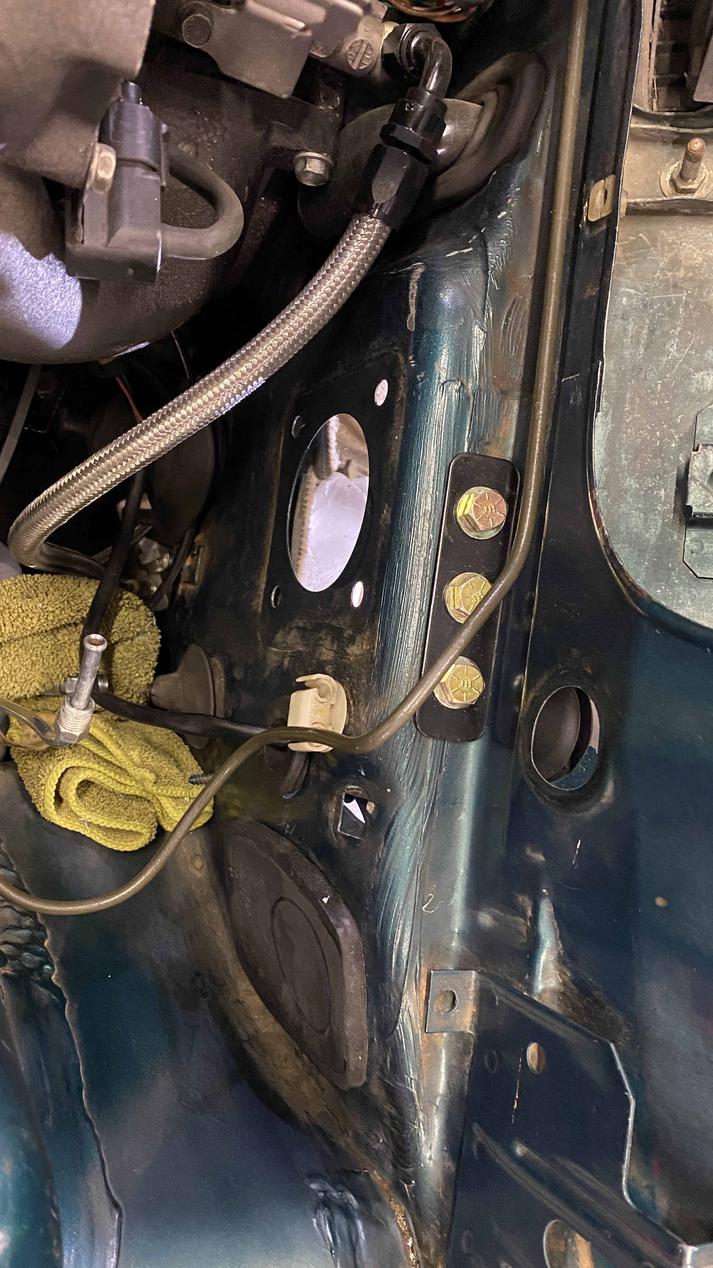
here’s a shot of the bracket and bolts that you have to drill into the firewall.
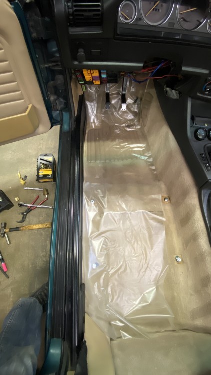
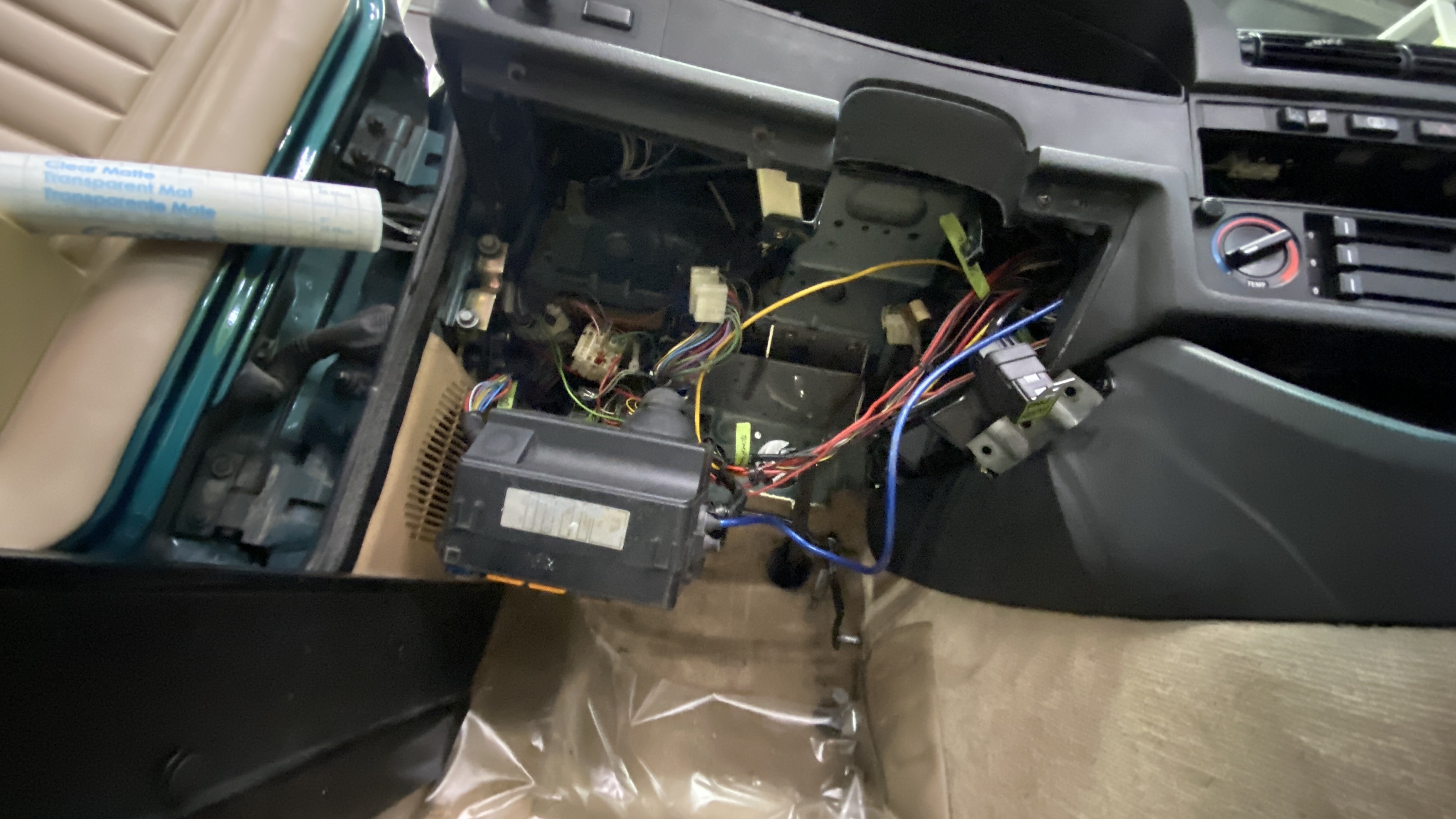
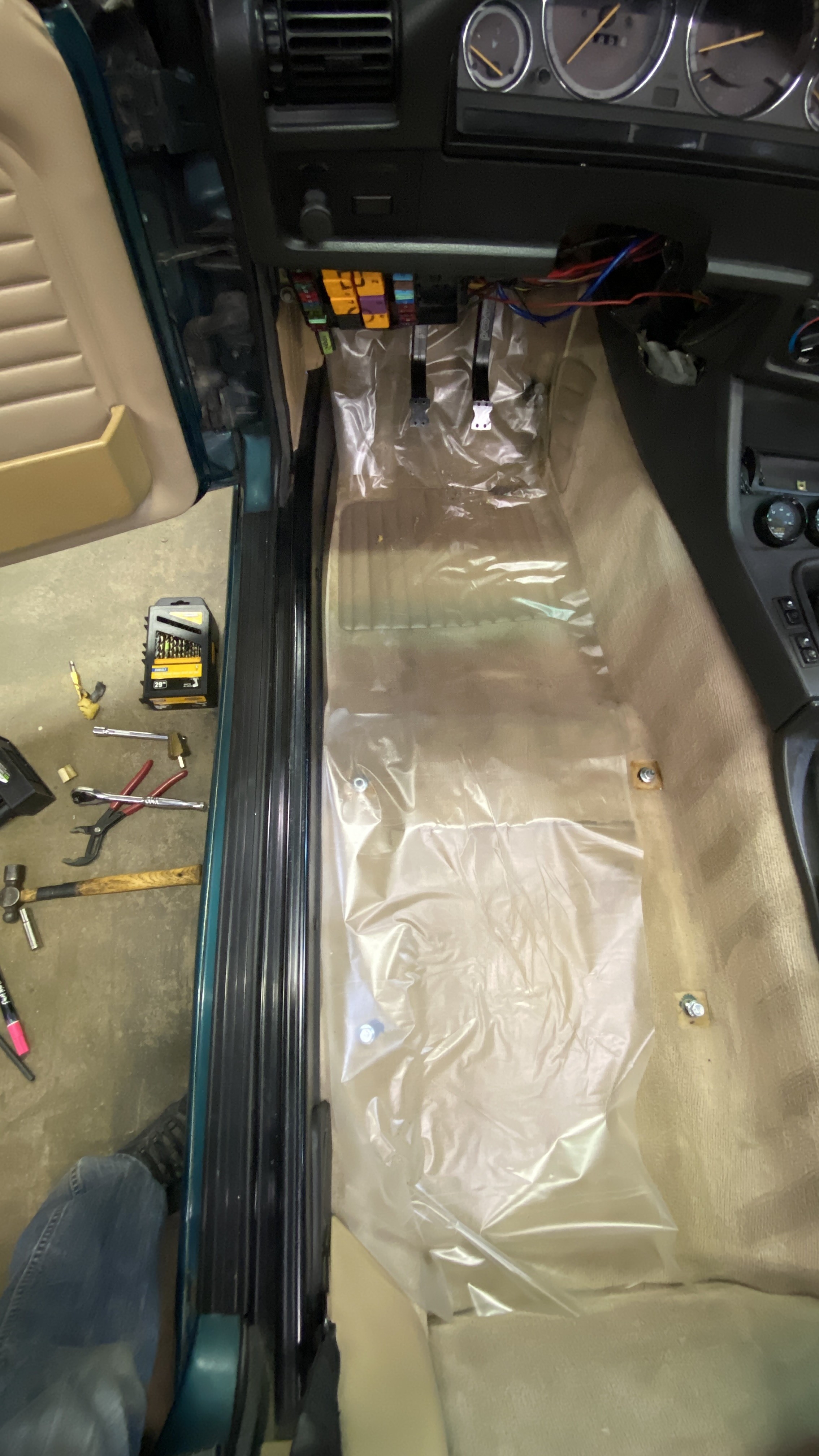
This last picture is just a picture of my carpet. I used drawer liners to protect the carpet from getting dirty as I’m crawling out from under the dash 40 some times fitting everything. I use this stuff all the time to protect surfaces. It doesn’t leave any residue and is around $3 for an entire roll of it.
https://www.instagram.com/_jdesigner_/ http://nevertoolow.tumblr.com/
🥳SOLD BMW E24 633CSI - BMW M30B32 🧪SOLD HCH ES9 - 1.3 LDA
👽BMW E30 325IC - Toyota 1JZ-GTE ⏰ HONDA EF9 CIVIC SI - JDM B18C5
☠️BMW E36 318i - Ford 5.0 FE302 🚴♂️ GT-Labomba - 26x2.75 Freeride
🤹♀️SOLD BMW E36/7 Z3 - BMW M54B25 🧓SOLD BMW E10 2002 - BMW M10M05 -
I don’t see how removing the dash would’ve been helpful except for maybe those 3 bracket bolts? You don’t gain much access with the dash supports still there which you had to work under for most everything. Nice progress!
I agree, It seemed really pointless. I can't imagine someone doing it and gaining much from it.
I tried to mount the column and it seems to run into the master towards the center of the car. I have a few leads on a early model column, but I am also considering a flaming river shaft to join the rack to the column in hopes to clean all of it up under the dash and in the engine bay.
https://www.instagram.com/_jdesigner_/ http://nevertoolow.tumblr.com/
🥳SOLD BMW E24 633CSI - BMW M30B32 🧪SOLD HCH ES9 - 1.3 LDA
👽BMW E30 325IC - Toyota 1JZ-GTE ⏰ HONDA EF9 CIVIC SI - JDM B18C5
☠️BMW E36 318i - Ford 5.0 FE302 🚴♂️ GT-Labomba - 26x2.75 Freeride
🤹♀️SOLD BMW E36/7 Z3 - BMW M54B25 🧓SOLD BMW E10 2002 - BMW M10M05 -
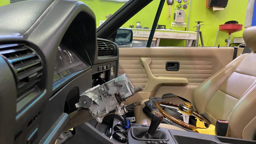
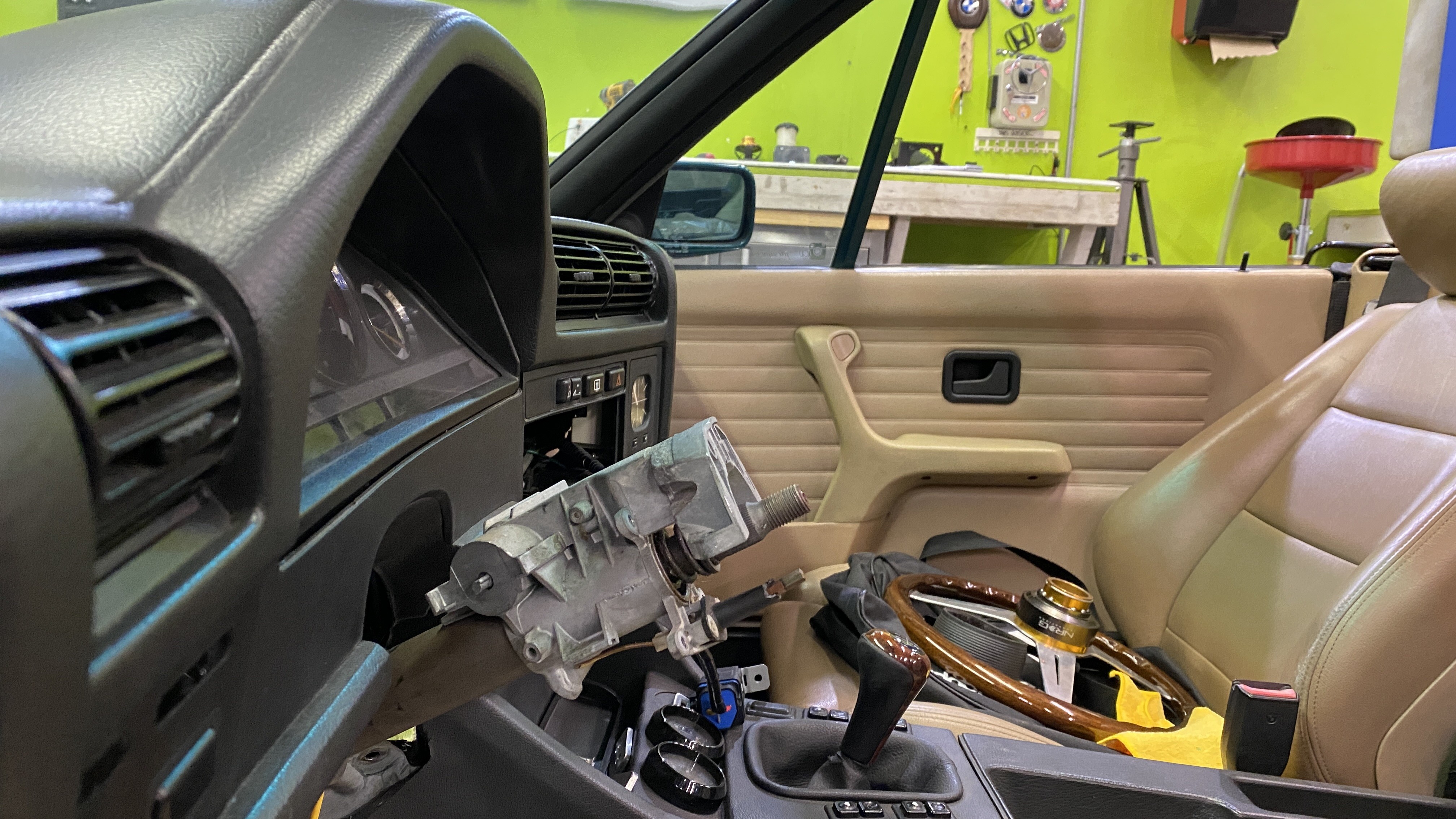
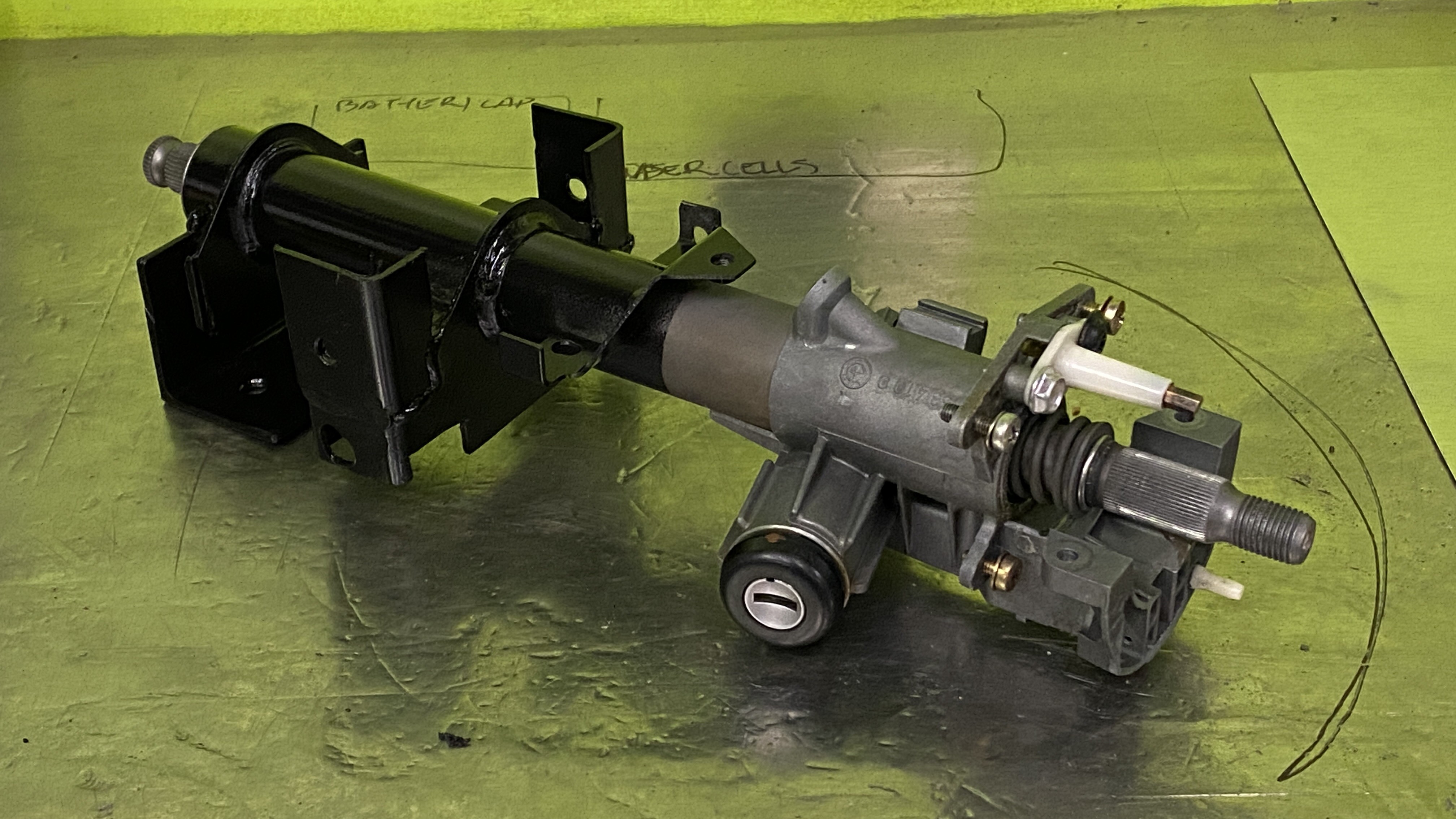
Well I spent most of my saturday trying to sort out my steering column issue. It turns out that none of my current options left me a happy camper. I did get myself an early model non-airbag column but the way it fit was very unfortunate. not only did it put the steering wheel angle back at the bus driver position that I hated, it also pointed the face of the wheel a good 5-10 degrees toward the drivers door. Apparently the hole in the firewall is different on the late model airbag cars.
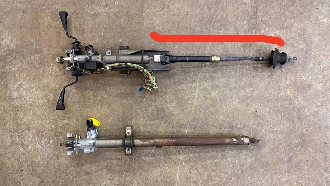
Here is the two columns side by side
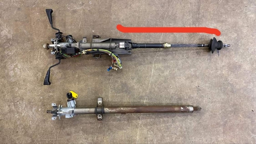
Here you can see how dramatically left the column faces

Here is the bus driver angle
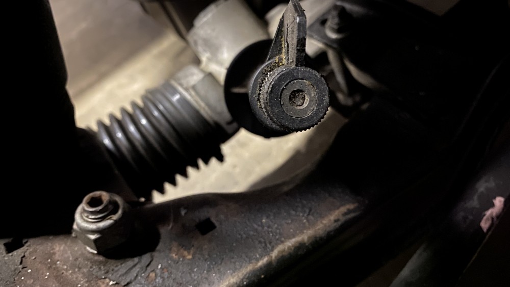
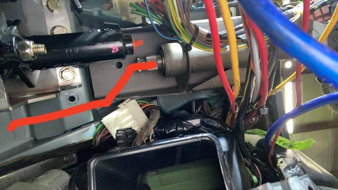
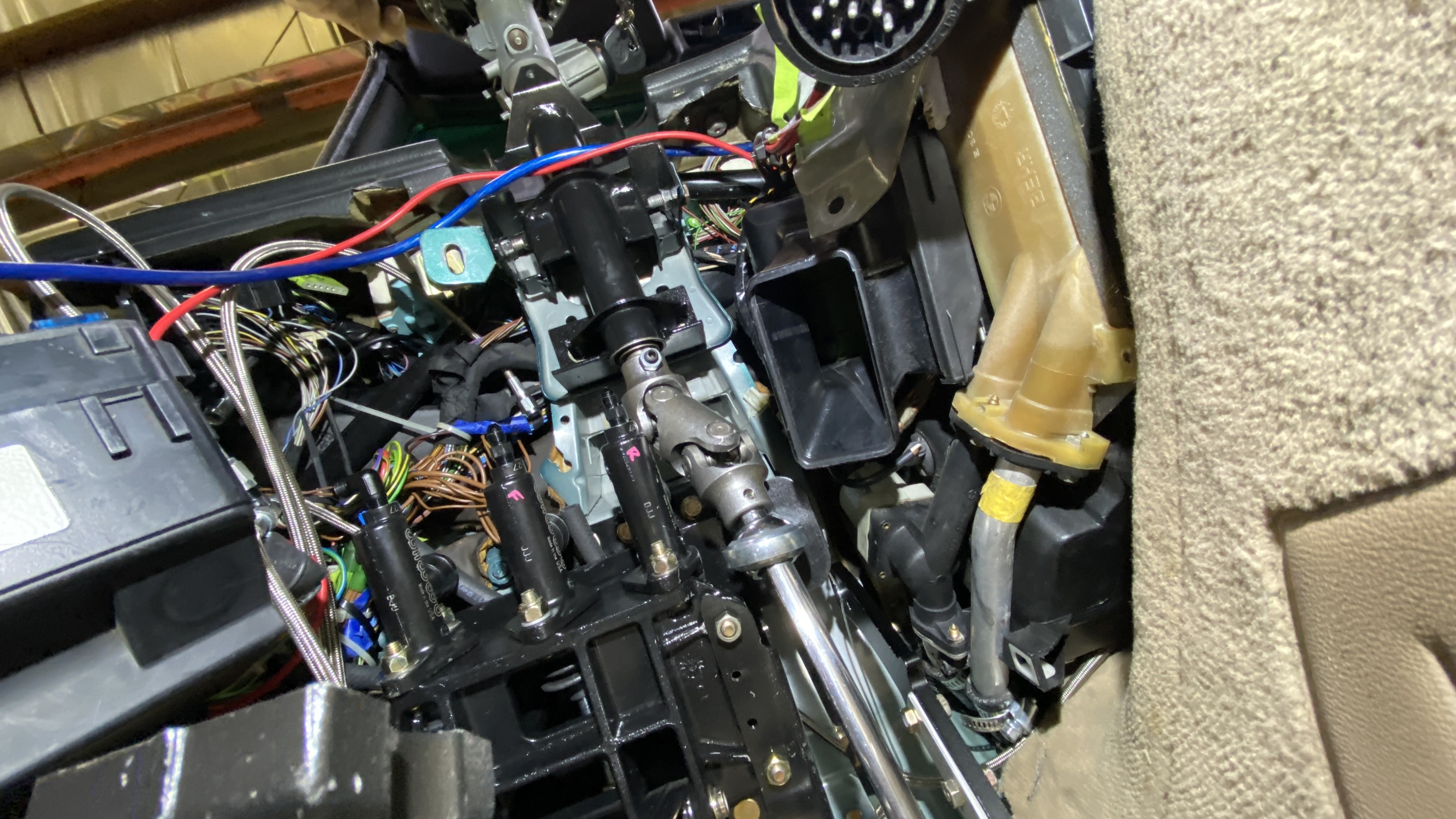
So my plan from here was that it would be easier to make my airbag column work. Below you can see how close one of the masters is to the splines of the column. I drew a line in red that shows where the shaft needs to go. Notice that my line is a "Z" as it not only has to go to the right, it also has to pivot down.
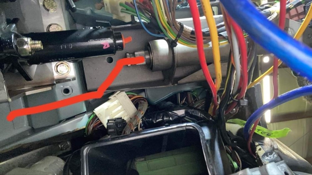
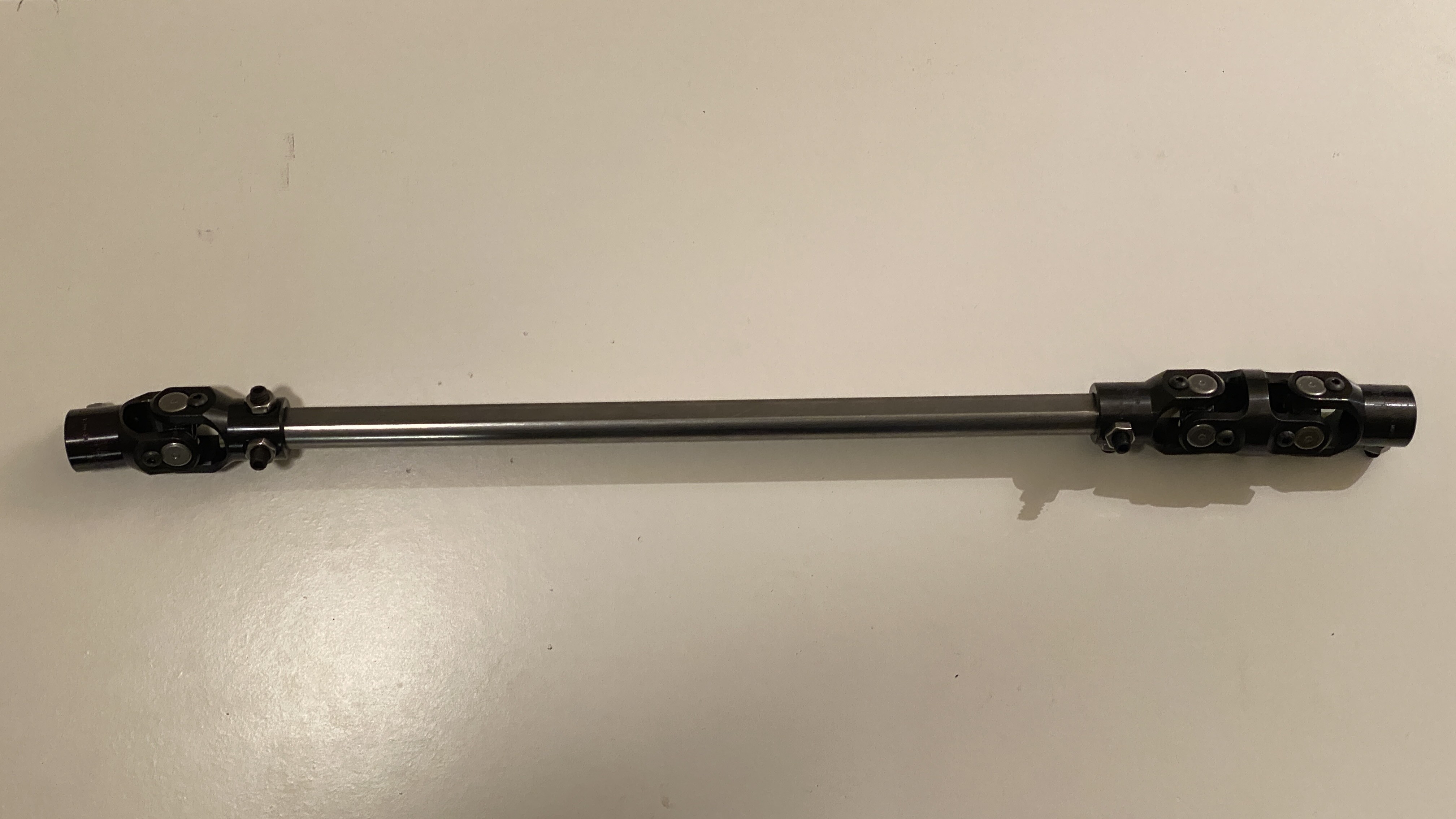
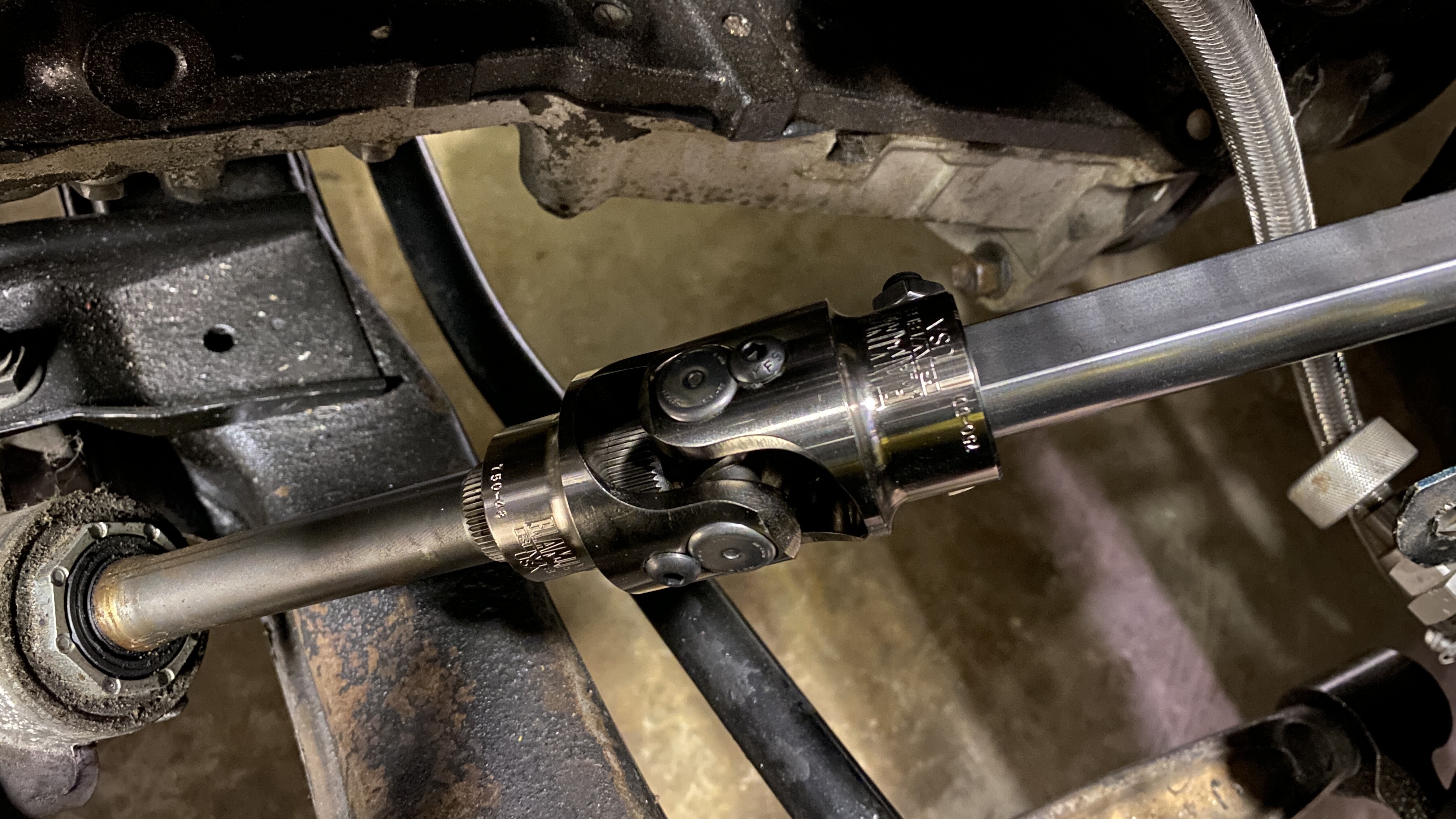
This is my solution; use a flaming river double U joint to make the "Z" and then a D shaft through the firewall and a second U joint to mate it to the Z4 rack. the second part im still not sure I have all the puzzle pieces yet. I previously made an adapter a few pages back in this thread to mate the Z4 to my column, but now I am using a D shaft, I will likely have to make a different adapter. I just ordered everything and will have to figure this out when I have everything in my hands.
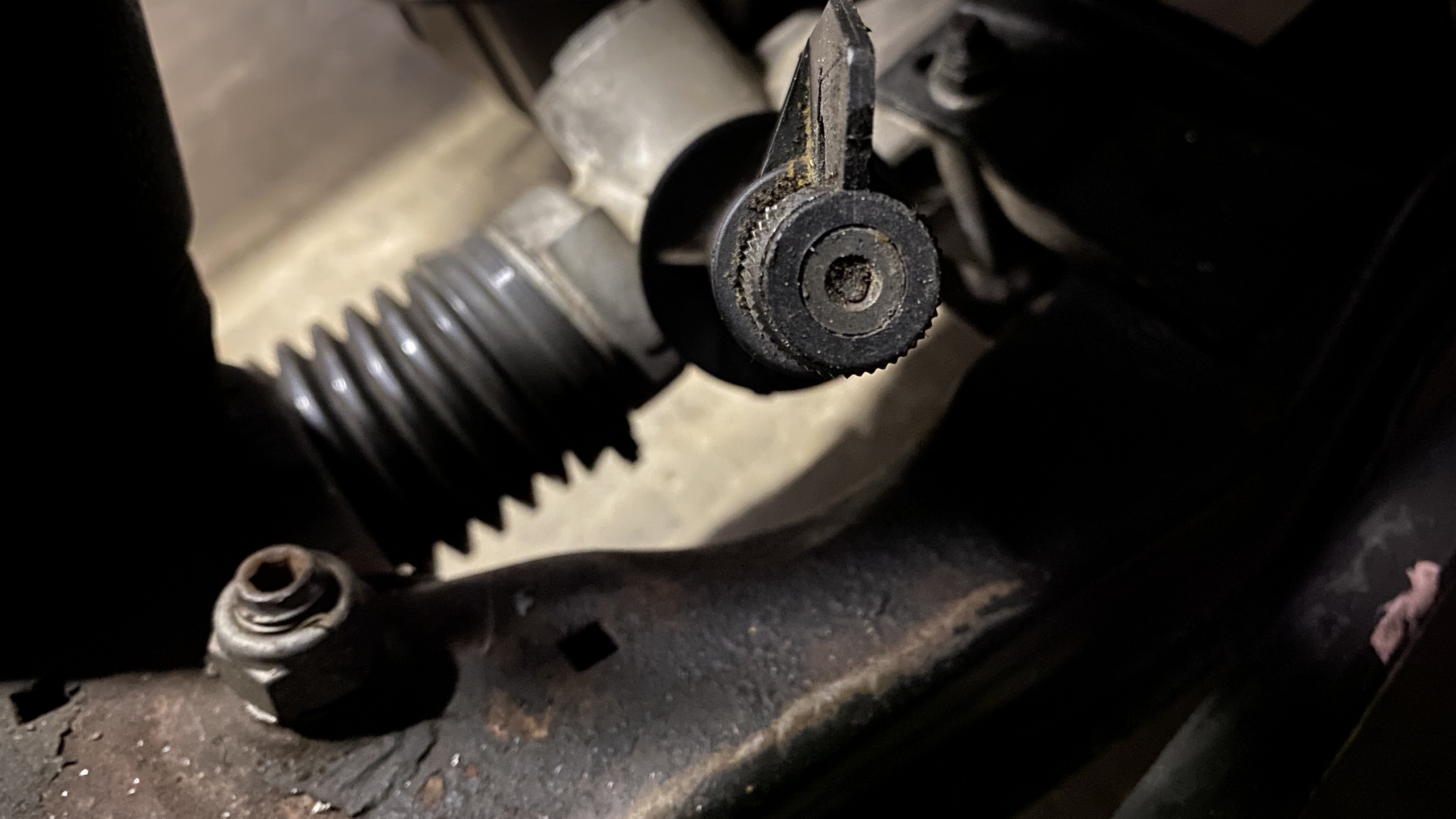
If anyone knows the spline count on the shaft of a Z4 rack, please let me know. I looked high and low and found nothing. it measures to 18mm on a caliper, but I had a hell of a time trying to get an accurate spline count. It is NOT the 17mm 54 spline that is commonly used.
https://www.instagram.com/_jdesigner_/ http://nevertoolow.tumblr.com/
🥳SOLD BMW E24 633CSI - BMW M30B32 🧪SOLD HCH ES9 - 1.3 LDA
👽BMW E30 325IC - Toyota 1JZ-GTE ⏰ HONDA EF9 CIVIC SI - JDM B18C5
☠️BMW E36 318i - Ford 5.0 FE302 🚴♂️ GT-Labomba - 26x2.75 Freeride
🤹♀️SOLD BMW E36/7 Z3 - BMW M54B25 🧓SOLD BMW E10 2002 - BMW M10M05 -
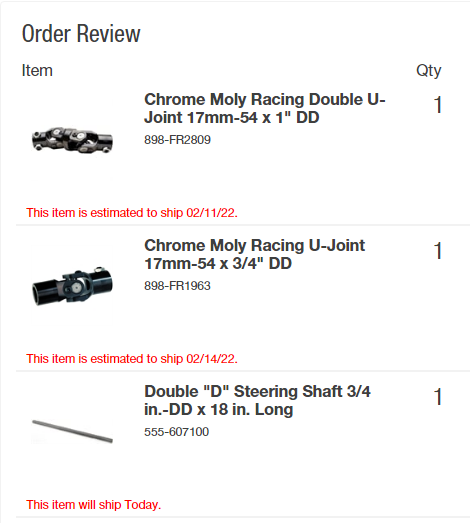
Welp. Parts came, and I’m an idiot ( which is evident) both joints I ordered were wrong. New ones are on the way now. Basically I read the specs off of R3v and just considered them accurate to my car without checking completely.
Here’s a picture of what I got, and sent back.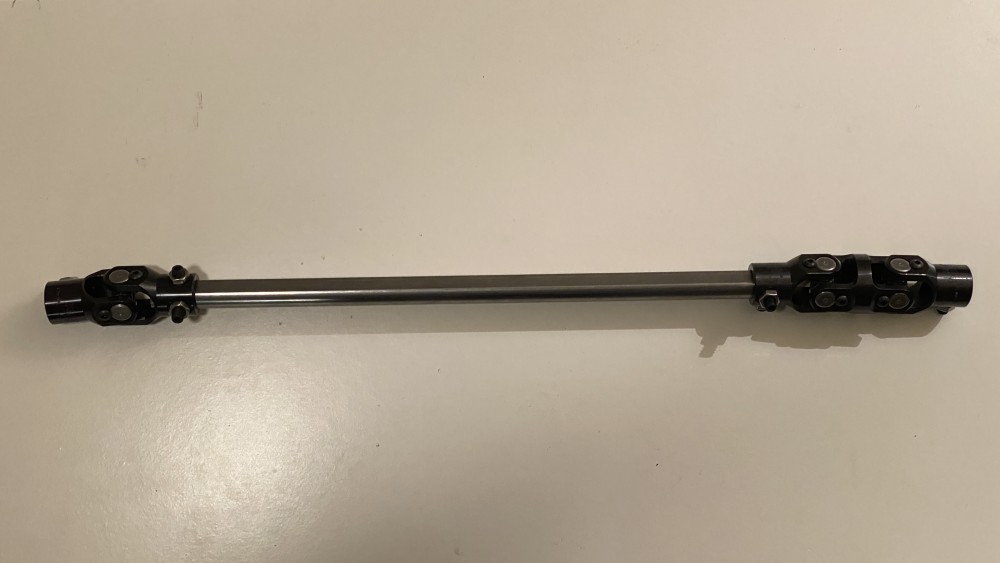
the correct (I think) sizes I ordered as are follows:
3/4” (19mm) -48 spline (z4 rack shaft specs) into a 3/4” D shaft
3/4” D shaft into
Double U (17.5mm)11/16” -36 spline (steering column specs)
——-
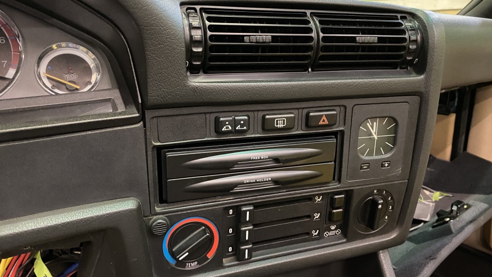
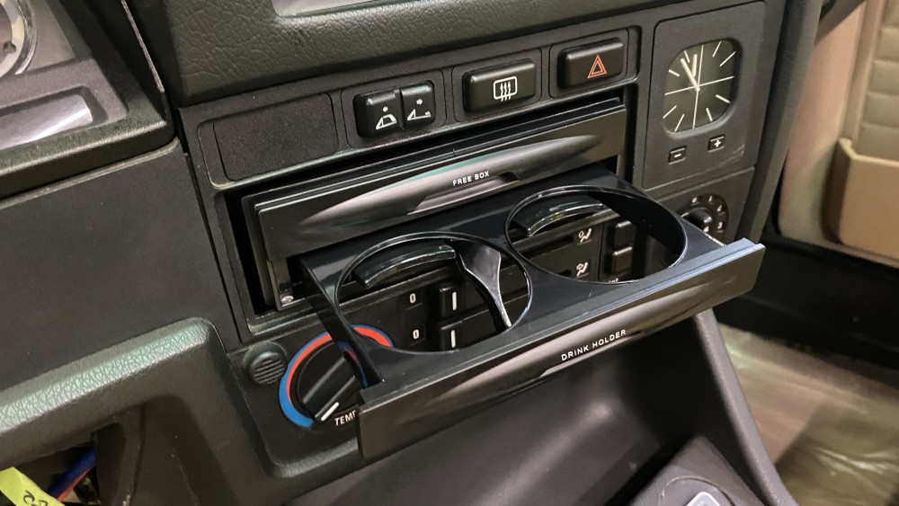
In other news, I ordered a replacement for my radio din since I have the Bluetooth amp. I will need to create a surround for it, and texture it to match the dash, but I think it’s a better idea than just a block off plate.
https://www.instagram.com/_jdesigner_/ http://nevertoolow.tumblr.com/
🥳SOLD BMW E24 633CSI - BMW M30B32 🧪SOLD HCH ES9 - 1.3 LDA
👽BMW E30 325IC - Toyota 1JZ-GTE ⏰ HONDA EF9 CIVIC SI - JDM B18C5
☠️BMW E36 318i - Ford 5.0 FE302 🚴♂️ GT-Labomba - 26x2.75 Freeride
🤹♀️SOLD BMW E36/7 Z3 - BMW M54B25 🧓SOLD BMW E10 2002 - BMW M10M05 -
In other news, I ordered a replacement for my radio din since I have the Bluetooth amp. I will need to create a surround for it, and texture it to match the dash, but I think it’s a better idea than just a block off plate.
That is awesome!!! I've been hearing more and more of people switching to those bluetooth amps and what a great addition to the interior of the car.
-
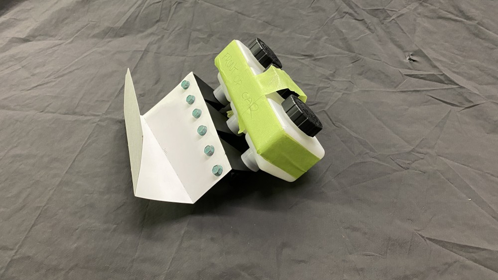
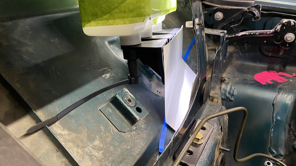
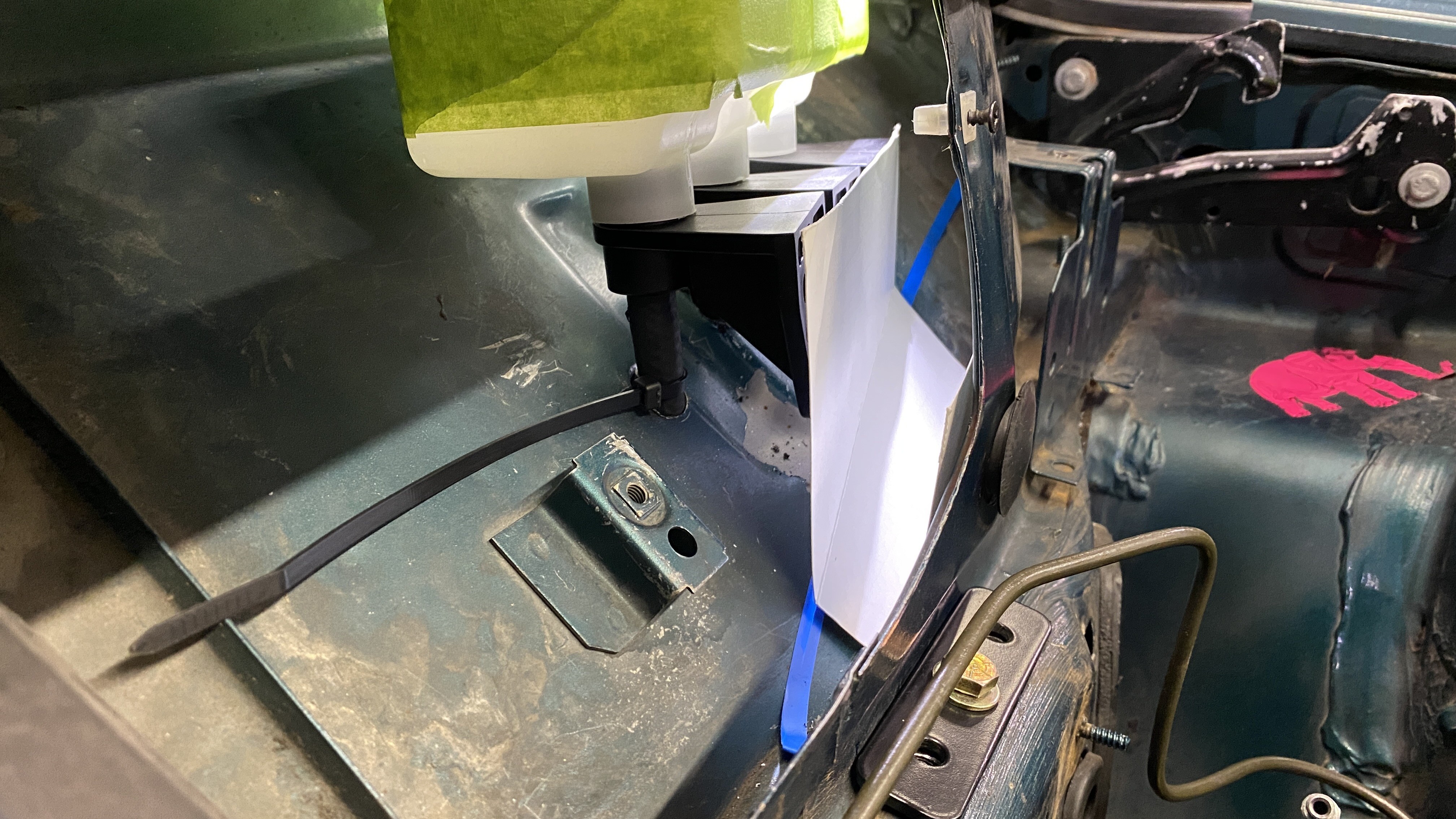
Mocked up a bracket to mount the reservoirs. I drilled the holes in the rain tray, added grommets and ran the lines to the masters. I ran into a small issue that I might be able to solve quickly once I pull everything back out again. The middle reservoir line is right where two layers of sheet metal split, so one side might need to be trimmed from under the dash. I am NOT looking forward to that.
The new joints showed up, and to my surprise, the second time is a charm. Everything fit perfectly! (Minus the fact that my D shaft is about 4" too short, HEH )
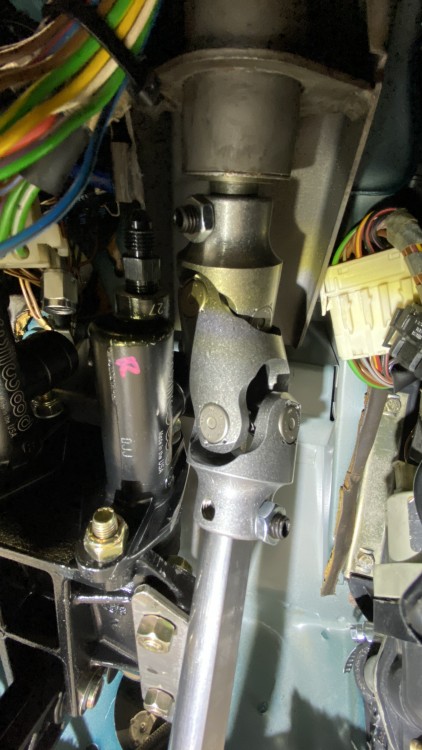
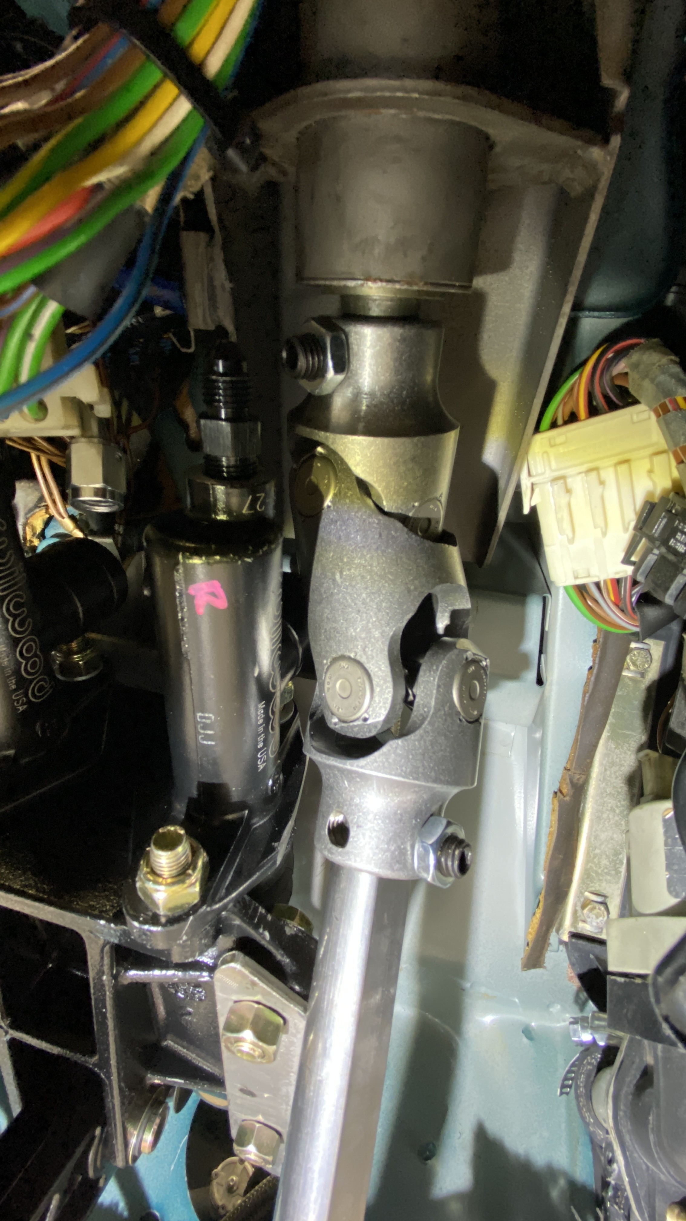
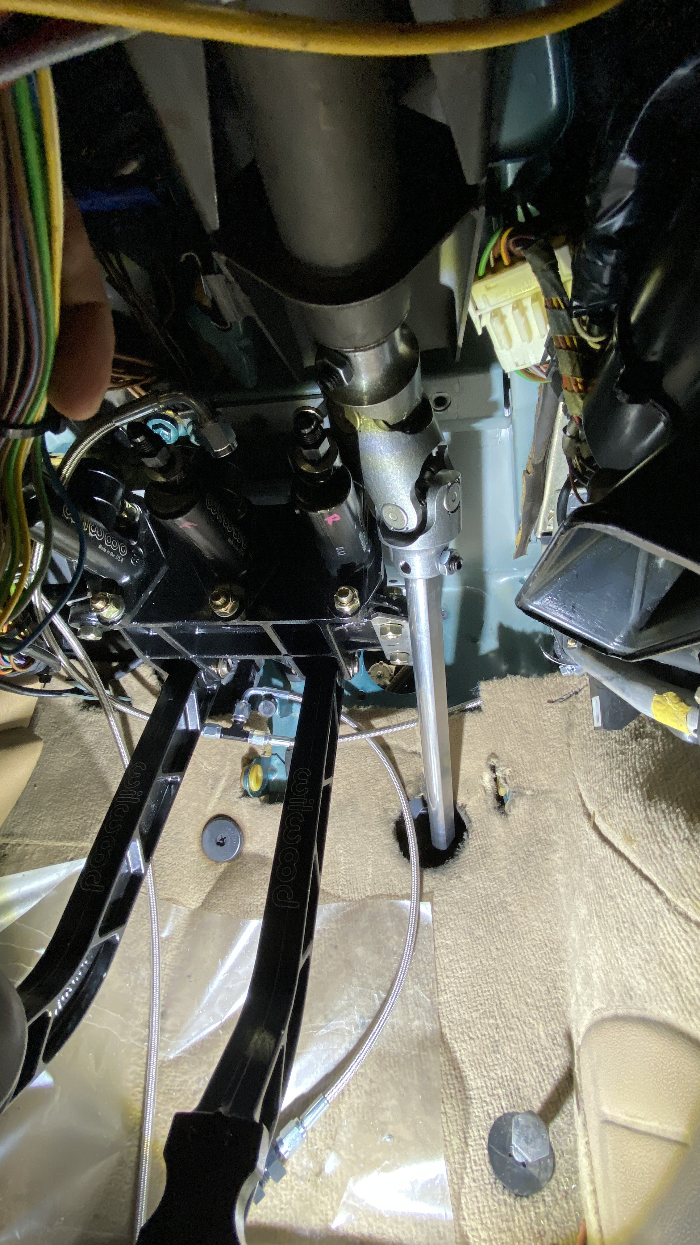
Under the dash its REALLY REALLY tight to the master. I actually had to shave the mounting bracket for the pedal box and the master itself to clear, but it looks like its going to work!
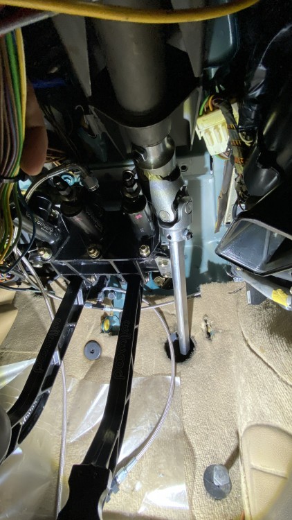
Here is the engine bay side of the D shaft and the new U joint to replace the one I made previously. It looks much nicer and is a lower profile than what I had.
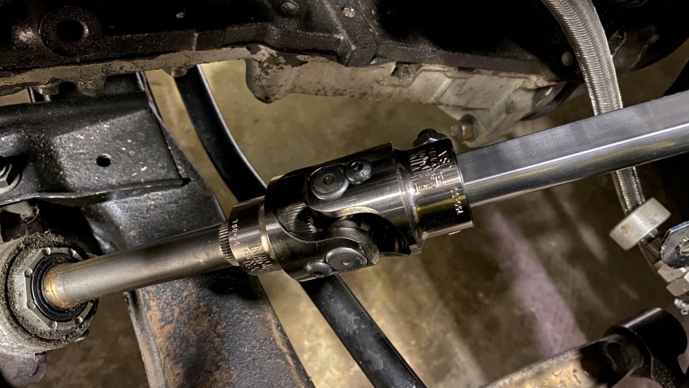
I ordered all the lines and fittings for the masters and started to mock all of that up as well. My biggest challenge with that is figuring out where I want to drill more holes for the bulk heads in the firewall. It already kind of looks like swiss cheese, and I figure I will weld all the holes shut once I paint the engine bay, but I rather get it right first than have to revisit it later.
https://www.instagram.com/_jdesigner_/ http://nevertoolow.tumblr.com/
🥳SOLD BMW E24 633CSI - BMW M30B32 🧪SOLD HCH ES9 - 1.3 LDA
👽BMW E30 325IC - Toyota 1JZ-GTE ⏰ HONDA EF9 CIVIC SI - JDM B18C5
☠️BMW E36 318i - Ford 5.0 FE302 🚴♂️ GT-Labomba - 26x2.75 Freeride
🤹♀️SOLD BMW E36/7 Z3 - BMW M54B25 🧓SOLD BMW E10 2002 - BMW M10M05 -
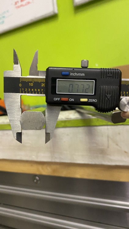
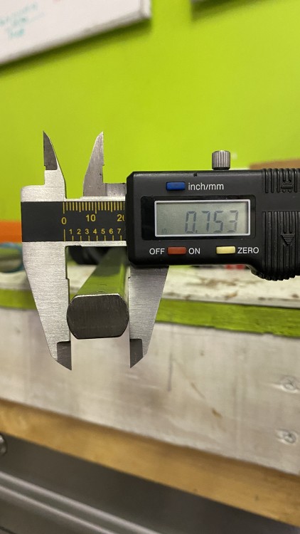
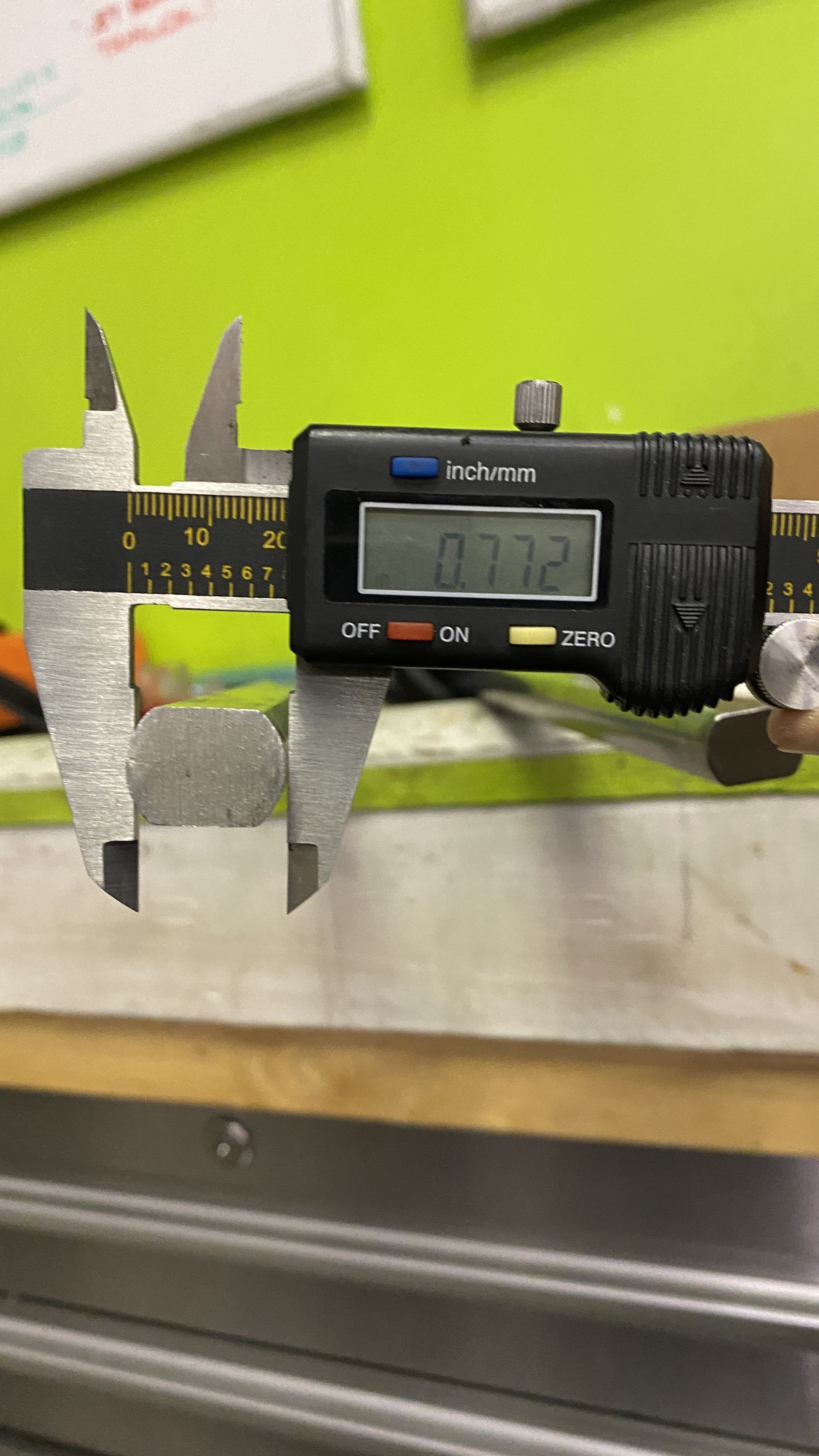
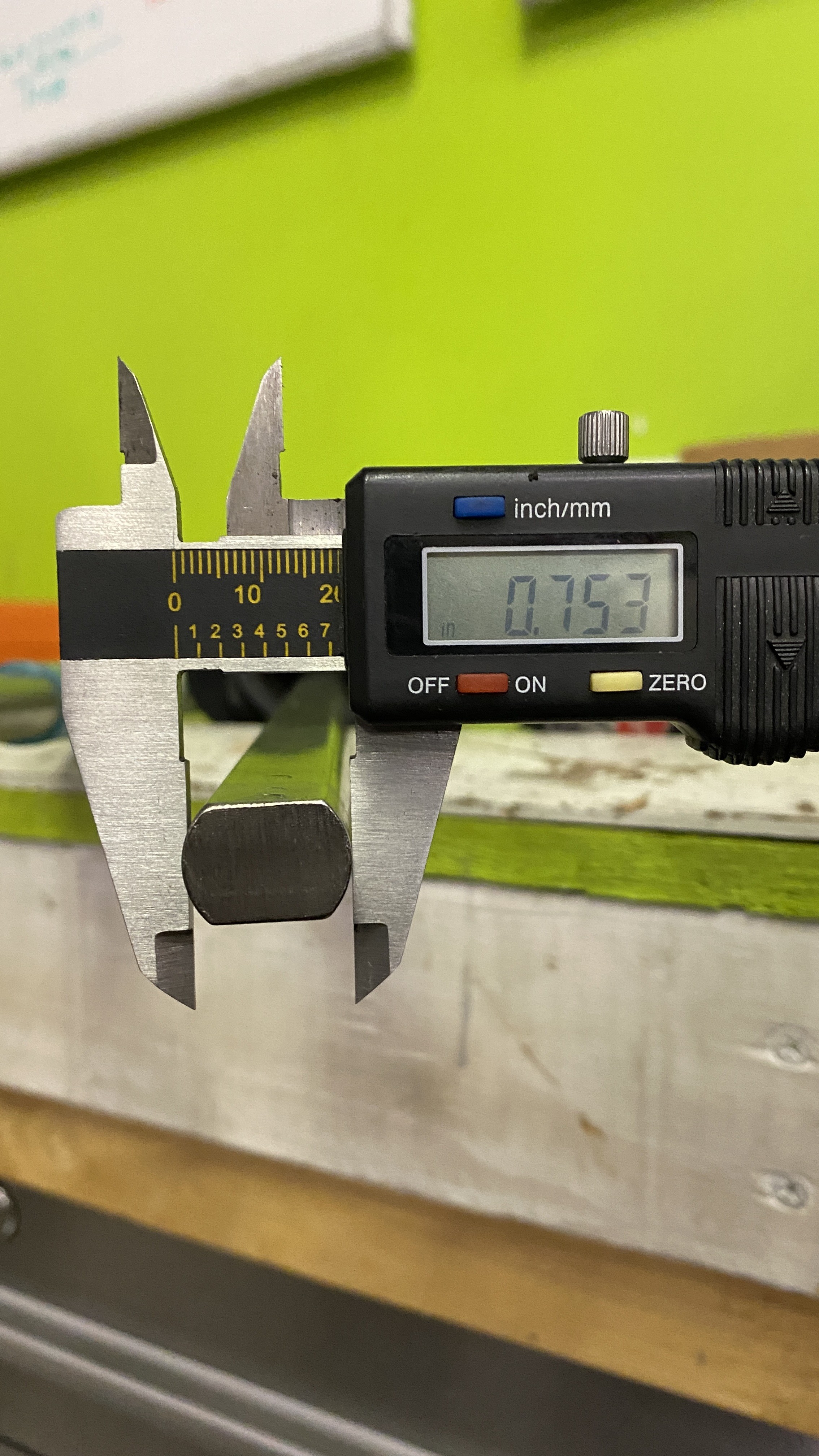
Wel, Ive still been plugging away at this. Lots of issues ordering the right parts, and fabrication to make everything work the way I want. The steering column has proved itself to be one hell of a pain in the ass. Partially my fault, but partially not. The latest issue was that the original shaft i ordered was roughly 4" too short. I knew it was going to be close, but when I placed my order, the option was 16" shaft or 48" which was way more expensive. I happened to find a shaft on ebay that was 48" for the same price as the 16" I bought. It showed up and as I should have expected it was a "oversized" part. apparently the supplier messed up and made a few thousand shafts 1m bigger than 3/4" and thats how the description read, but not the listing title. UGHH
I ended up machining the D shaft down and cut it to length. Here is what I got:
Here is what it should have been:
After that bummer, I kind of hit a dead end for the steering and brakes until I got the column mounted. I needed to make sure the angle was correct, so that once I machined the shaft and cut it down, it was a good fit. This literally took days of cutting, welding, and measuring. I didn't take any pictures, but I will be adding some eventually. Once I get the column in and everything mocked up, I will be cad modeling a new steering column bracket based on my dimensions and getting parts from Sendcutsend to weld it all together. (unless someone has access to a laser or water jet?)
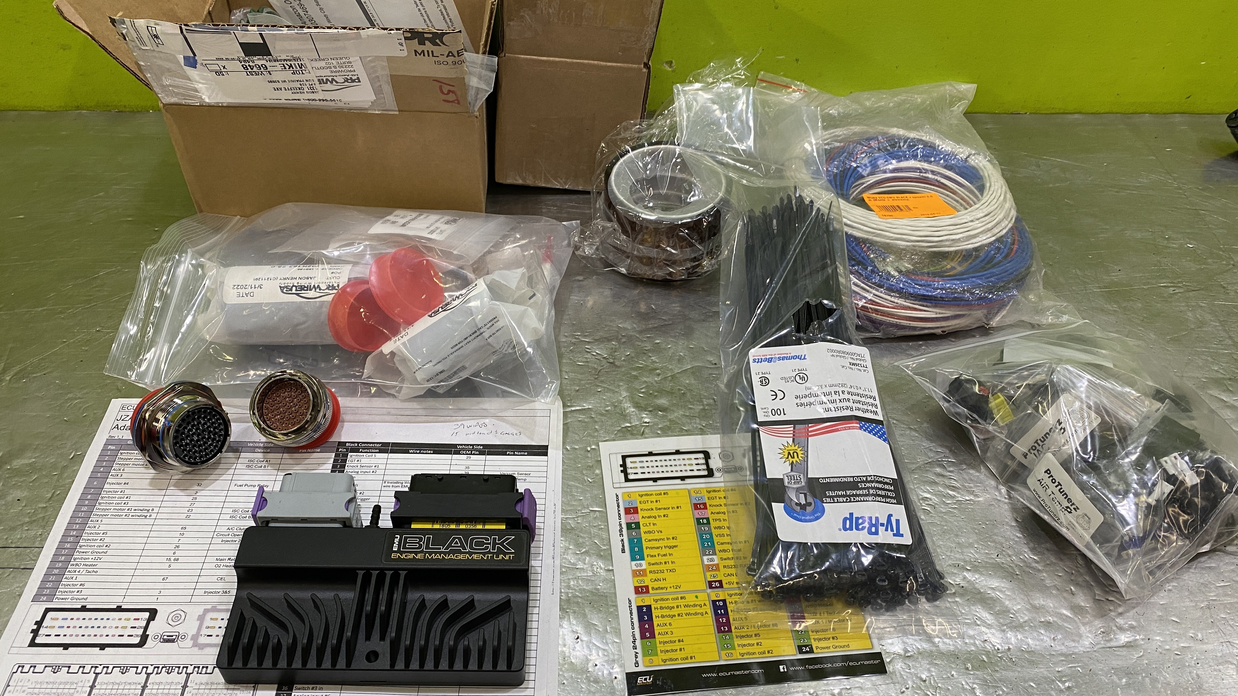
So I started pulling the engine harness. I forgot how simple and easy this harness was. It might look like a mess, but it took me about 20mins to have everything out and on the workbench. I cant wait to build a new harness for this thing.
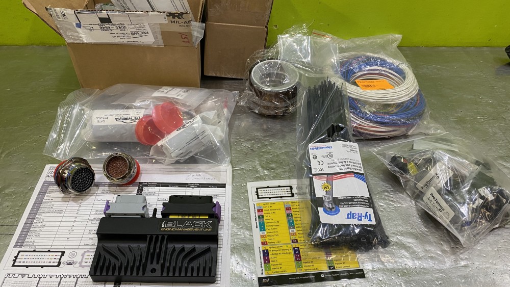
So once I had the harness out, my main objective was to figure out what Mil-spec firewall plug I would need. I had to figure out how many wires would pass through the plug, and plan for any possible updates as these plugs are expensive. I geeked out and spent a good weeks worth of time reading this site: https://www.rbracing-rsr.com/wiring_ecu.html and researching and ordering materials for building the harness. I HIGHLY recommend reading through that site, as it has tons of information on building high quality wiring harnesses.
Here is some of the stuff I ordered:
- Ty-rap metal tab'd not marring zip ties
- Full 1jz plug kit. this has every connector I need with pins and gaskets
- Kapton antistatic tape in various sizes
- Magnetic polymer magnetic jaws for my vise to use while spinning the leads
- Zip Tie Mounts for laying out the harness
- Nylon coated wire for temp tying wire bundles
- Deutsch DTM 12 Pin Connector for my injector harness ( I plan to upgrade later and this will allow me to without having to rebuild the harness
- 61 way Mil-Spec connector kit with plug/receptacle connectors , shrink boots and shrink boot adapters.
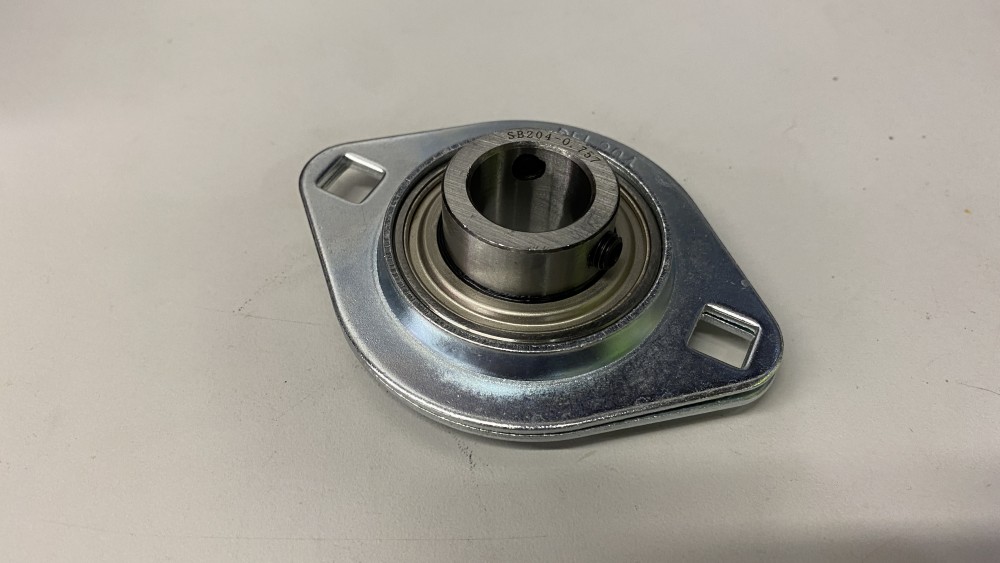
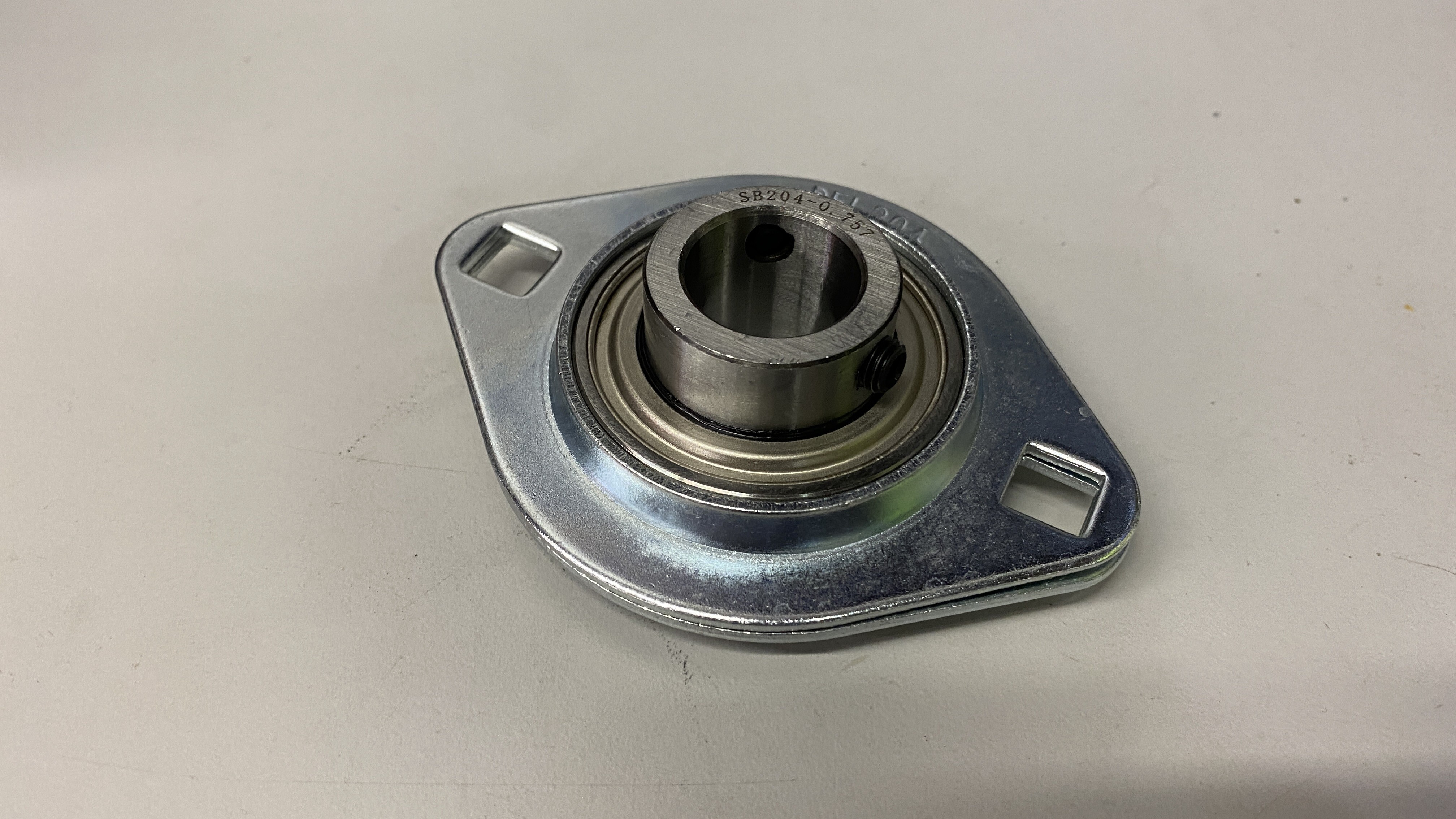
Finally as of today my firewall support bearing for my steering shaft showed up, and it the last part I needed to check the steering off of the list. Due to using dual U-joints for my steering, a support bearing is needed to prevent binding. In addition to that, this will also help seal the hole in the firewall that the shaft passes through.
https://www.instagram.com/_jdesigner_/ http://nevertoolow.tumblr.com/
🥳SOLD BMW E24 633CSI - BMW M30B32 🧪SOLD HCH ES9 - 1.3 LDA
👽BMW E30 325IC - Toyota 1JZ-GTE ⏰ HONDA EF9 CIVIC SI - JDM B18C5
☠️BMW E36 318i - Ford 5.0 FE302 🚴♂️ GT-Labomba - 26x2.75 Freeride
🤹♀️SOLD BMW E36/7 Z3 - BMW M54B25 🧓SOLD BMW E10 2002 - BMW M10M05 -
I used the same type of steering joint from Condor (I think you actually sent me the link when I had found the stock one was all bound up) and that came the same way. I had to very carefully remove some material from it so it could slide together. Super annoying for a $300 part.
And SendCutSend is who I have been using for all of my headlight parts. They're awesome and have been so helpful when I had issues exporting DXF files.
-
I used the same type of steering joint from Condor (I think you actually sent me the link when I had found the stock one was all bound up) and that came the same way. I had to very carefully remove some material from it so it could slide together. Super annoying for a $300 part.
And SendCutSend is who I have been using for all of my headlight parts. They're awesome and have been so helpful when I had issues exporting DXF files.
I have heard nothing but good things about them!
https://www.instagram.com/_jdesigner_/ http://nevertoolow.tumblr.com/
🥳SOLD BMW E24 633CSI - BMW M30B32 🧪SOLD HCH ES9 - 1.3 LDA
👽BMW E30 325IC - Toyota 1JZ-GTE ⏰ HONDA EF9 CIVIC SI - JDM B18C5
☠️BMW E36 318i - Ford 5.0 FE302 🚴♂️ GT-Labomba - 26x2.75 Freeride
🤹♀️SOLD BMW E36/7 Z3 - BMW M54B25 🧓SOLD BMW E10 2002 - BMW M10M05 -
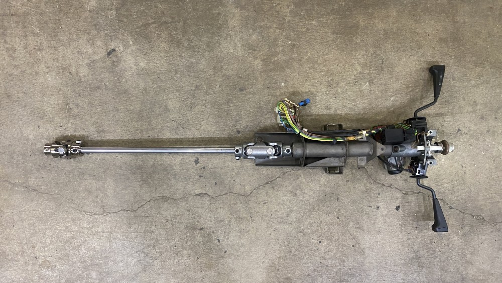
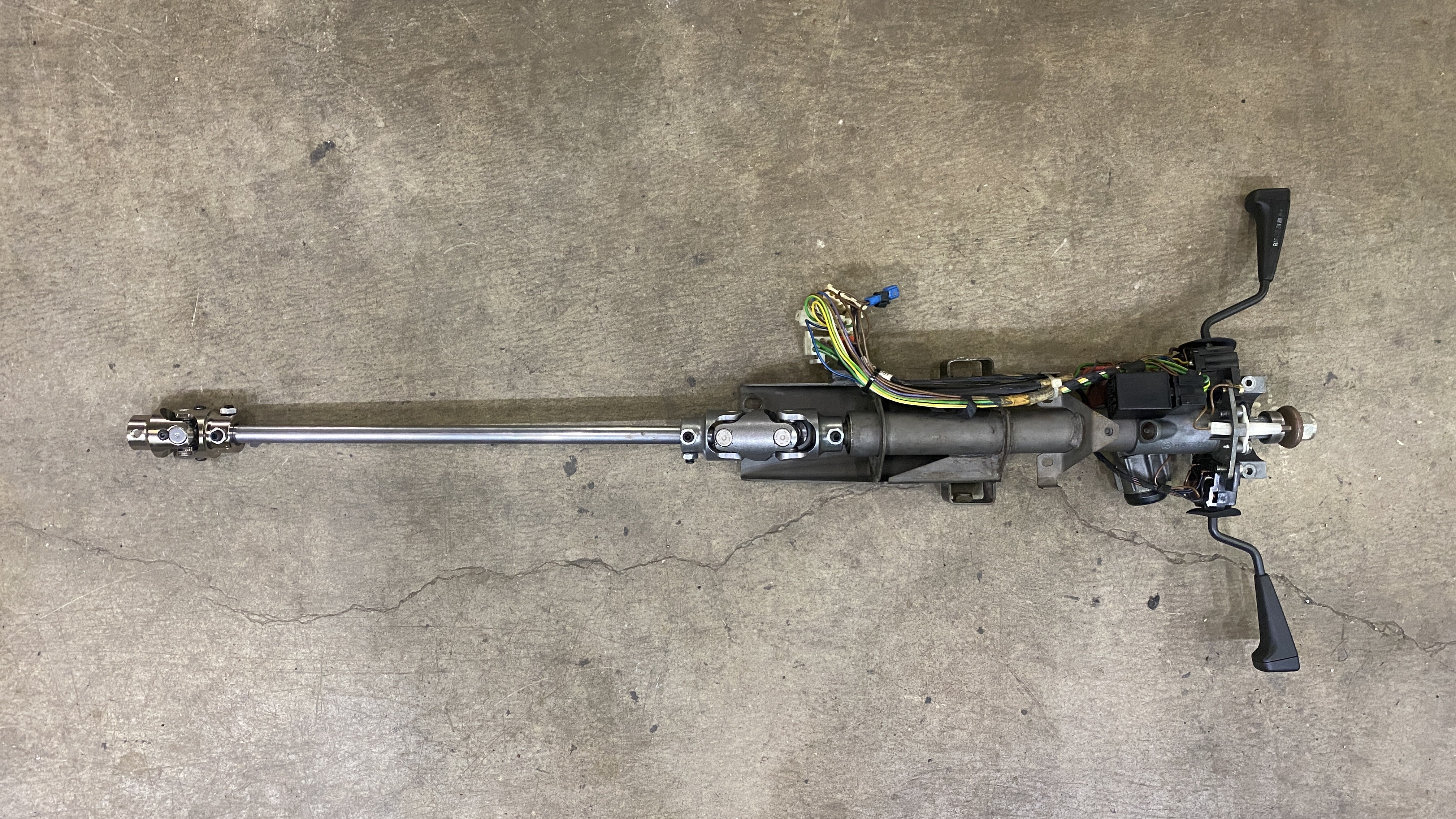
Still fighting this car as much as I can. As of yesterday, I think I can say the steering is complete. Sadly, I needed to add a secondary support bearing closer to the double D joint as it would bind under certain conditions. To do this meant I could no longer use the shaft that I had machined down and had to get yet another D shaft. Luckily I had a friend with a spare sitting in his shop that was the right size and length, and was also chrome plated. I was able to mount everything where it needed to be, and welded a new bracket to the pedal box bracket for the new support. After that I added an additional bracket to the column as well to replace the factory support under the dash cluster. This last bracket made everything much much stronger. Finally the steering "inside" the car is done.
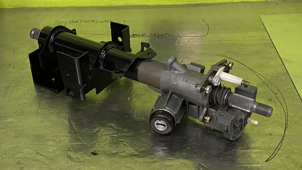
If you look close here you can see the L bracket right at the back of the column that would make that final rigid support.
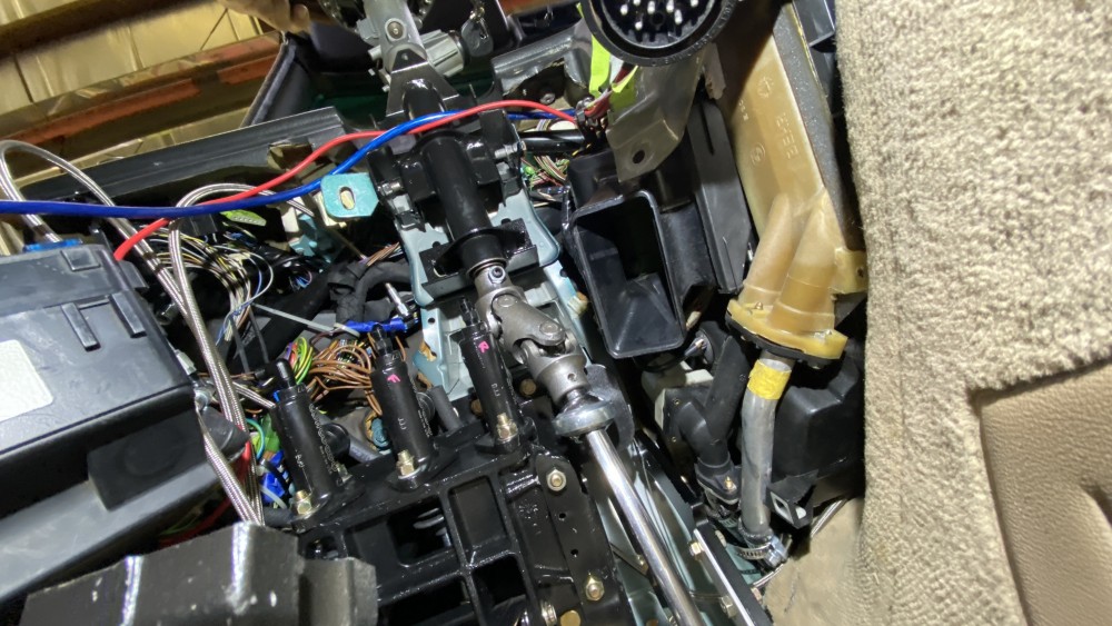
The next thing I needed to attack was getting all the bulkheads in the firewall and the braided brake lines ran. Most of these were already routed earlier, but I will need to add adel clamps so they aren't flying around. One that I did not install was the clutch line. I was waiting to do this as I wanted to hide most of the bulk heads and this one was near the steering shaft and the throttle. I had to complete these in order to prevent any more redos.
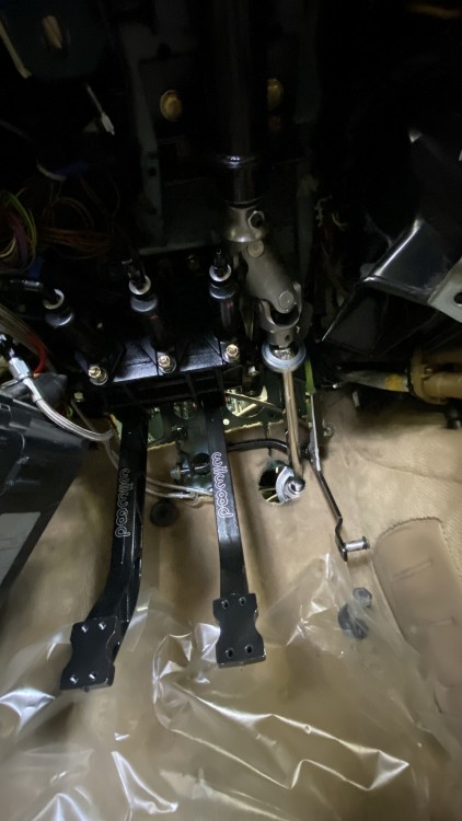
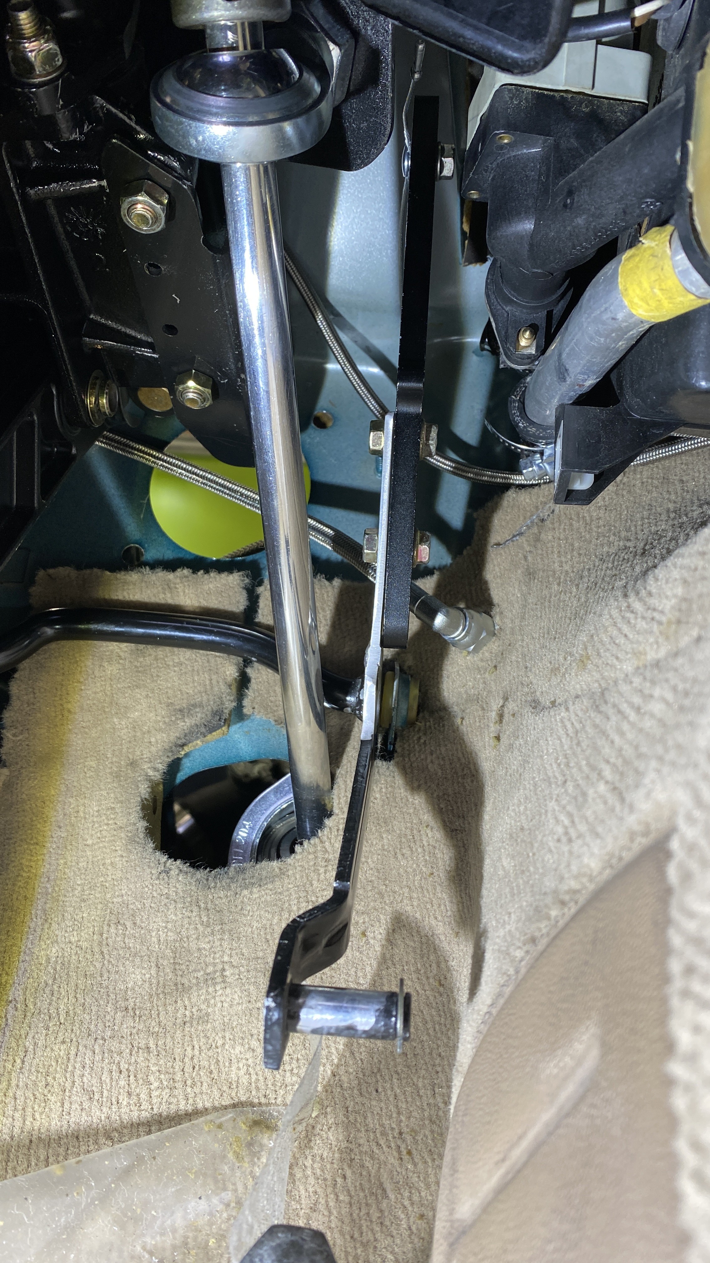
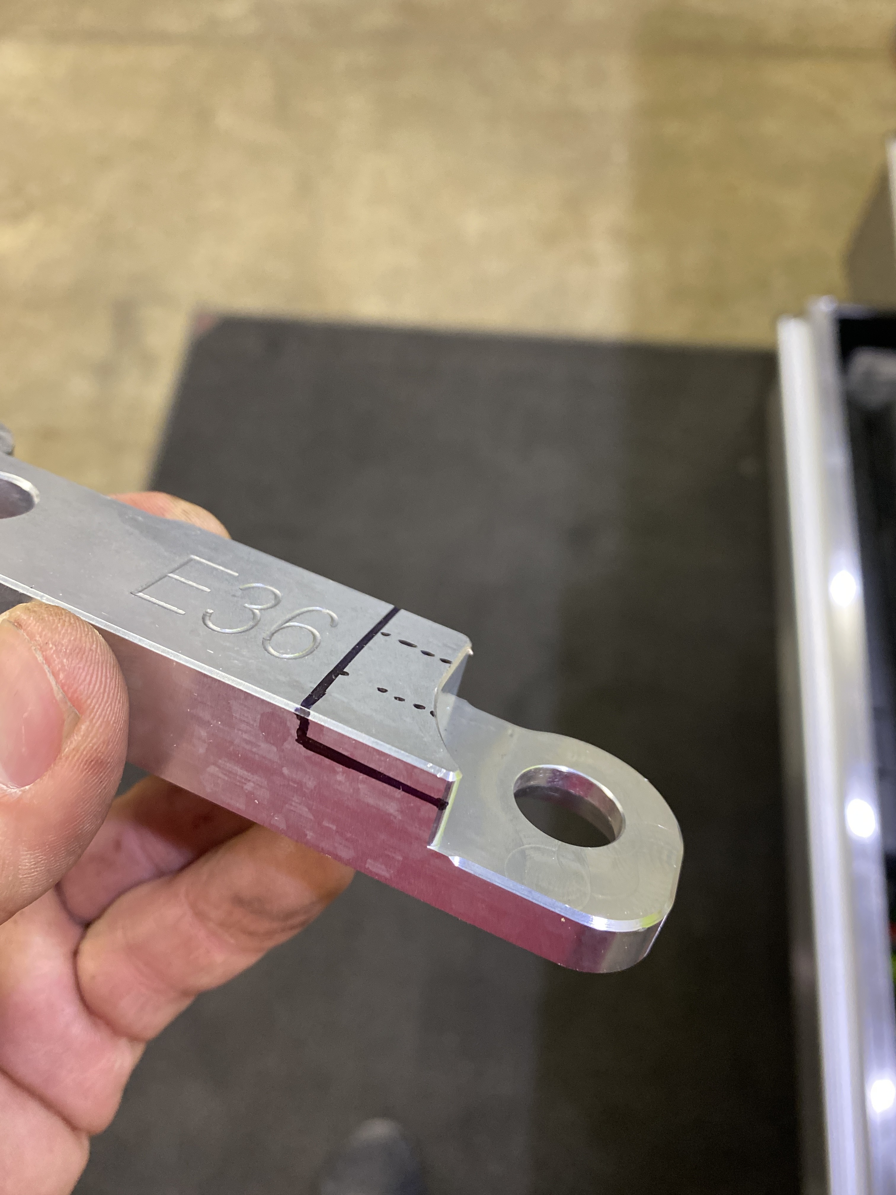
So first up I had to modify the throttle for the pedal box. The throttle beam and cam is made of aluminum, and the pivot travels behind the steering shaft and the brake pedals. The cable from factory exits just above where the clutch pedal is, and with the new pedal box, this needs to be moved. I cut the cable arm right above the factory stop to maintain the correct pedal height, and added material approximately the same height directly above the throttle pedal itself. This would allow the cable to be located closer to the center of the engine bay and directly inline with the throttle body. I was able to reduce the length of the cable by about 12" with this alteration!
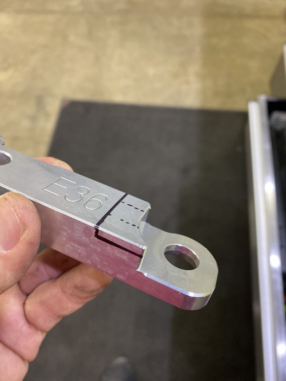
What I didn't expect was that with the cable location to the cam profile on the pedal, was that I now would need about an extra 2-4" of leverage from the fulcrum to completely open and close the throttlebody. So my solution was a billet aluminum lever from a cheap hydro that I could make an adjustable extension. This worked perfect, and actually made everything much more sturdy.
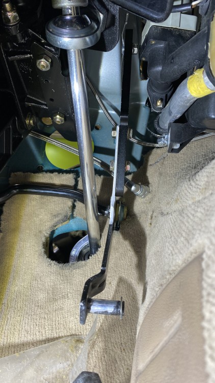
Finally I ran the clutch line bulkhead right below the heater core lines beside the throttle. The angle of the picture below gives you an idea on the location, and also how tightly everything fits together. Note the cable at the top of the lever and the space on either side as it passes through when the throttle is depressed.
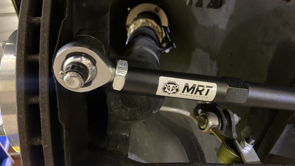
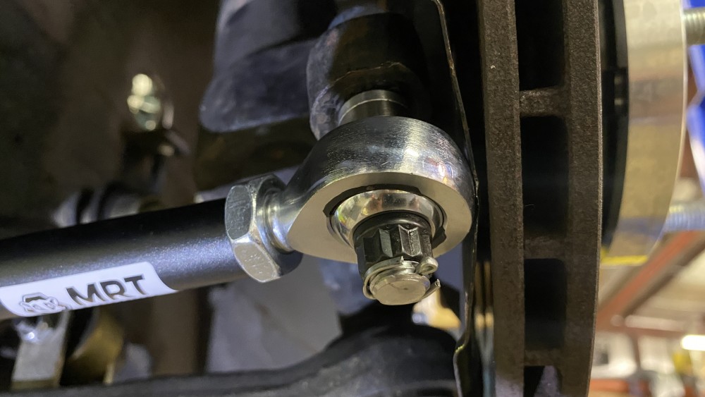
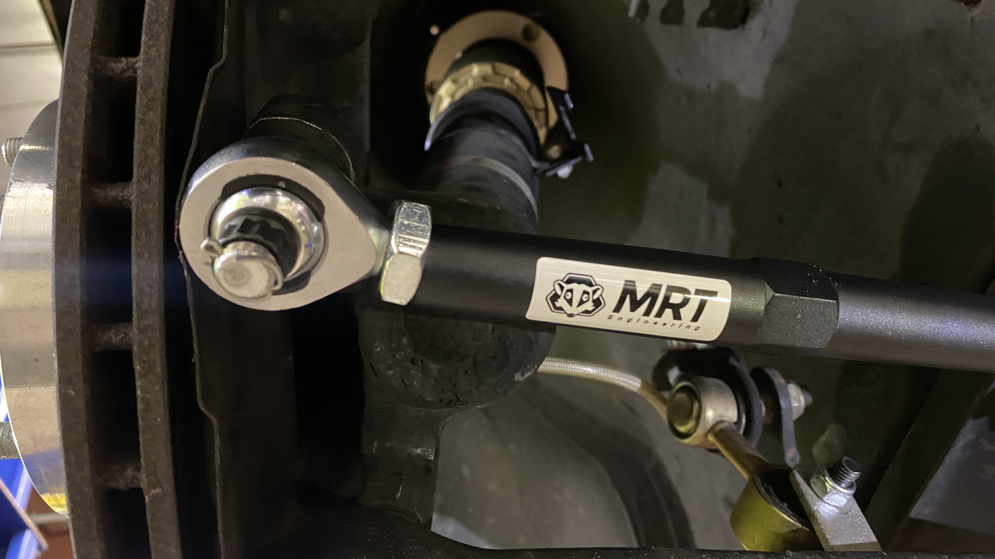
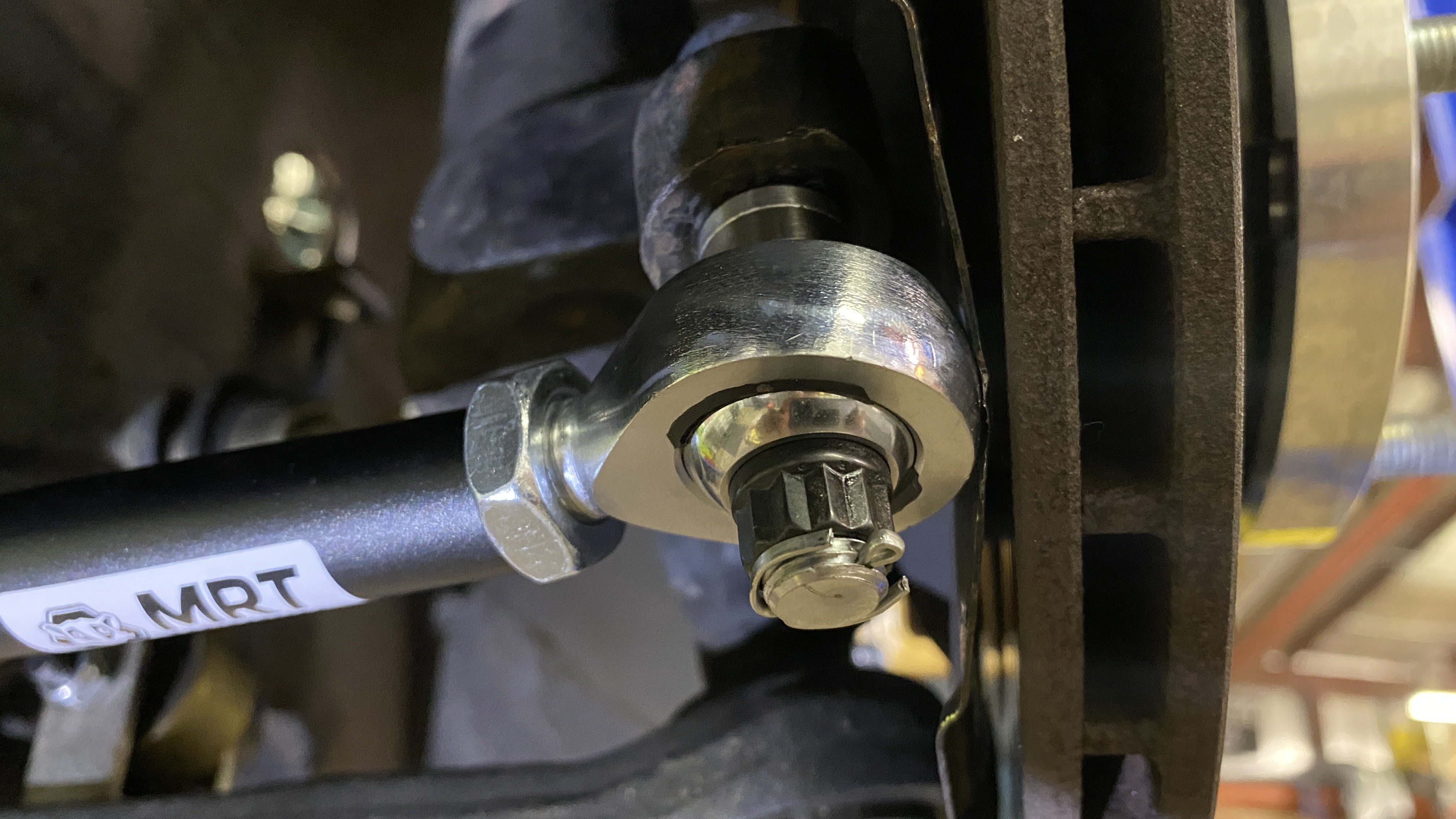
On the exterior of the steering issues was something I didn't mention previously. The new Wilwood rotors sat much further inward to the hub and were very close to the heatshields. So close in fact that with the factory tie rods installed, the boots pushed the shields into the rotors and would cause them to rub. I tried to get different tie rods and even shave them down, but that didn't help. I then bought an cheap angle kit like the one on my E36 to move the pivot inward and away from the rotor. The kit I bought didn't quite fit the hubs I have, so I had to mill them down on the Bridgeport. This was a fail, as even after machining them, I would need additional spacers on the brackets and special hardware. Ultimately I caved and bought a bump steer kit that uses Heim joints in place of the tie rods that allowed me the extra space. I figured these will also help with bumpsteer (duh) and the car being so low and not having power steering anyways.
See failed E36 bracket below
And the MRT bumpsteer kit installed. Note the space between the heatshield and rotors.
Next is wiring. I started, but its nothing worth mentioning just yet. Fingered Crossed for the Picnic!
https://www.instagram.com/_jdesigner_/ http://nevertoolow.tumblr.com/
🥳SOLD BMW E24 633CSI - BMW M30B32 🧪SOLD HCH ES9 - 1.3 LDA
👽BMW E30 325IC - Toyota 1JZ-GTE ⏰ HONDA EF9 CIVIC SI - JDM B18C5
☠️BMW E36 318i - Ford 5.0 FE302 🚴♂️ GT-Labomba - 26x2.75 Freeride
🤹♀️SOLD BMW E36/7 Z3 - BMW M54B25 🧓SOLD BMW E10 2002 - BMW M10M05 -
P R O C R A S T I N A T I O N
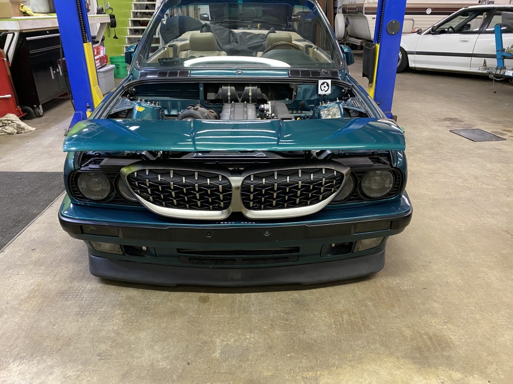
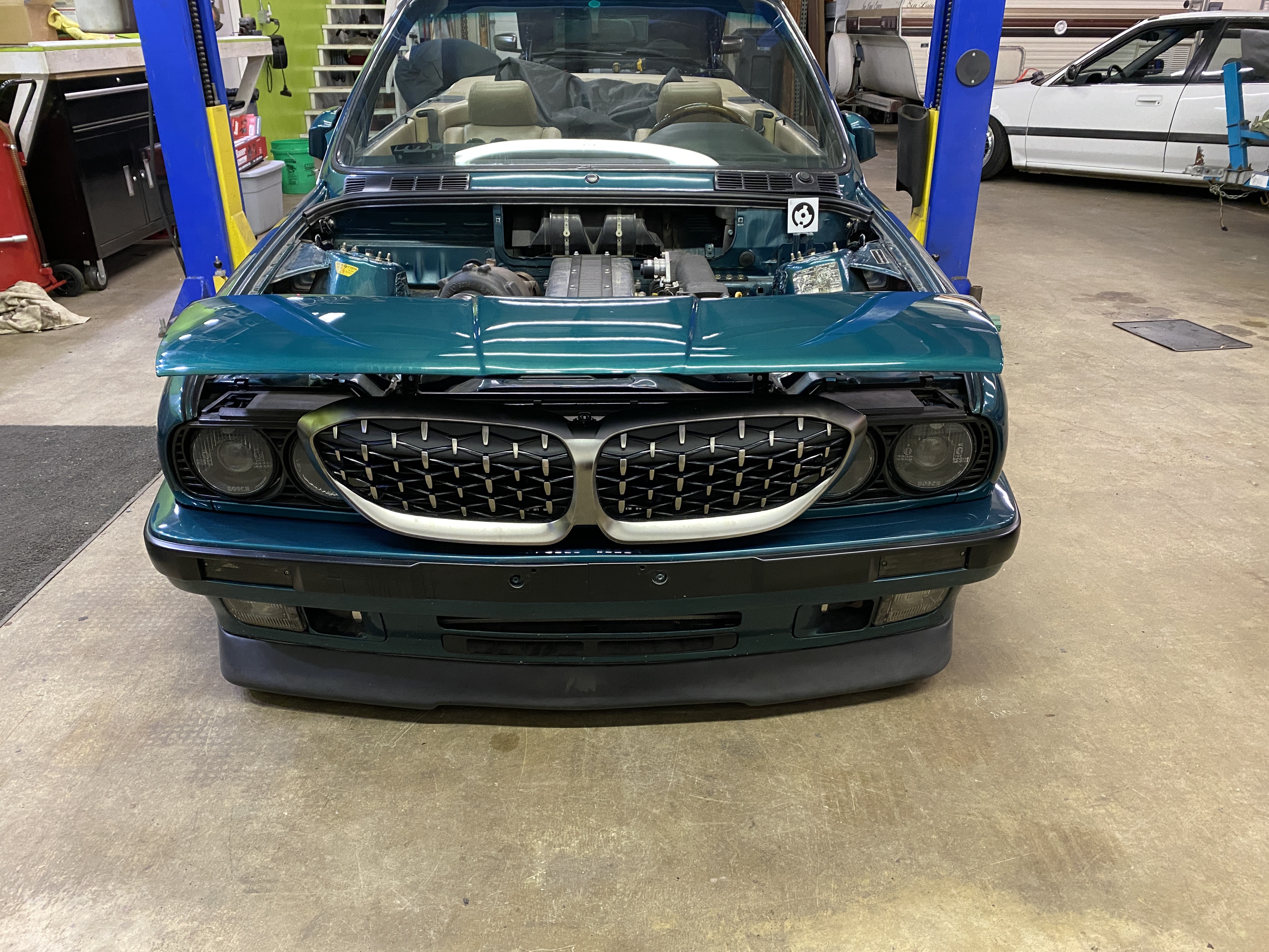
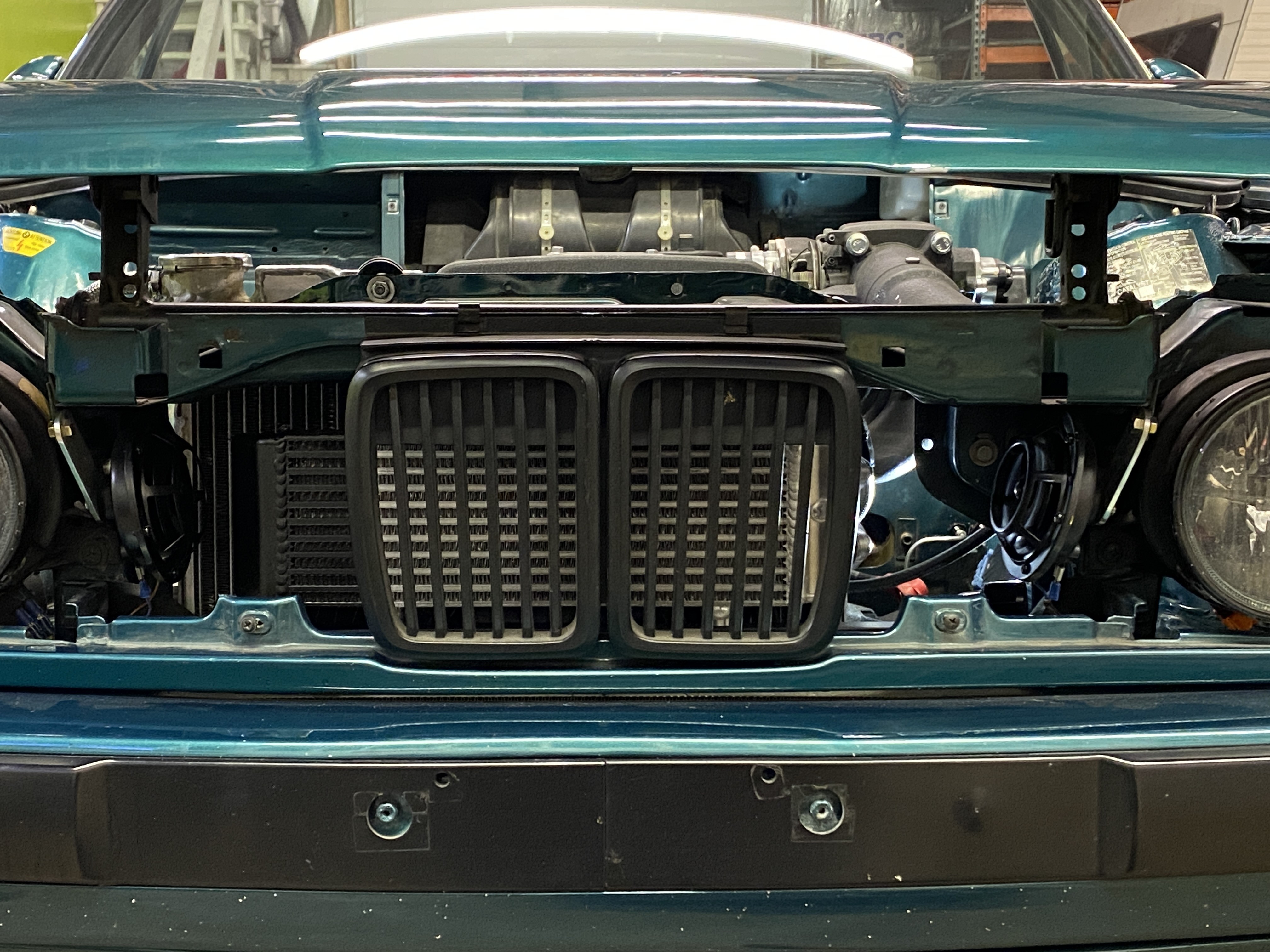
Yeah so I didn't really work on the harness. BUT! I have accomplished some other things. I had Tim come by and 3D scan my engine bay which was a pretty neat ordeal. I wanted to get a CAD file of my engine bay and hardtop for reference files to allow me to create models for reinforcing my firewall, filler panels to give the bay more symmetry, and the hardtop to build a jig for the Lexan. Tim also traded in his F90 M5 Comp for a G20 M340 and he wanted to swap grills right away. So for fun, this is what 7th gen 3series grills look like on a second gen 3series E30.
Anyways I also got around to ordering and installing some more parts. I finally finished up relocating the fuel lines because of the steering shaft / starter interference. I unfortunately think I will end up redoing these lines because they are still factory 8mm -5/16 hardlines up until they get to the bottom of the firewall where I adapted them to braided -6AN that goes to the fuel rail and regulator. I think that once I get the car running again and start tuning I will add more fuel and boost, and the 8mm factory lines will limit my flowrate. But for now, its good till I cross that bridge.
(Sorry I have no pictures of this)^^
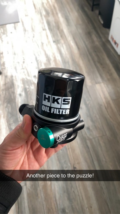
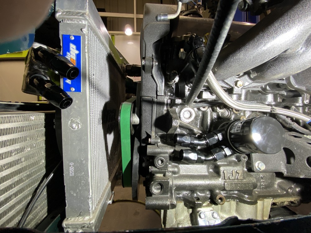
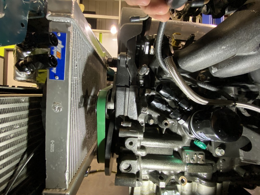
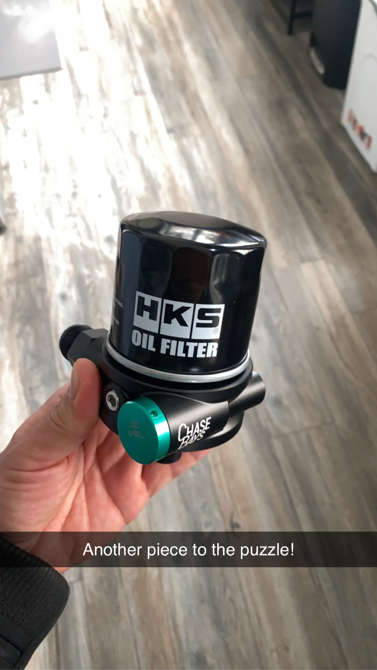
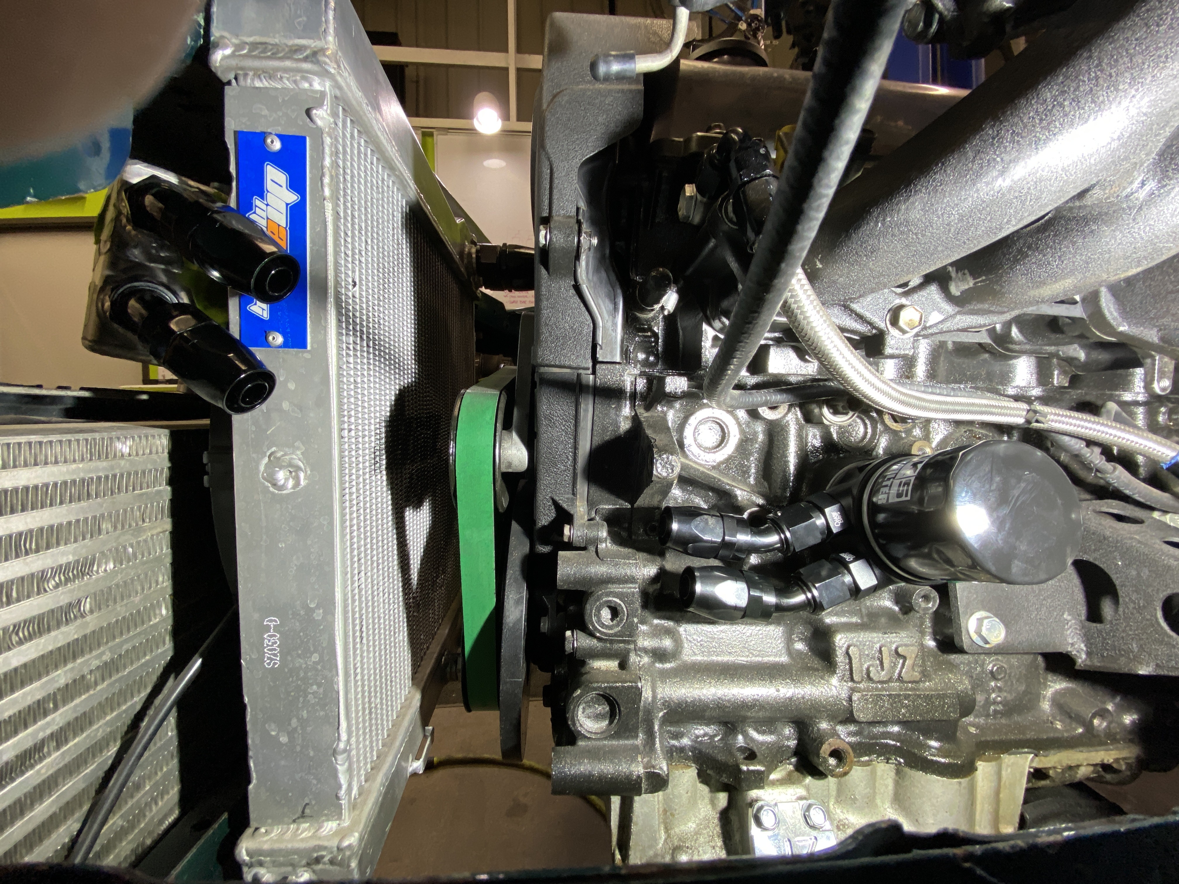
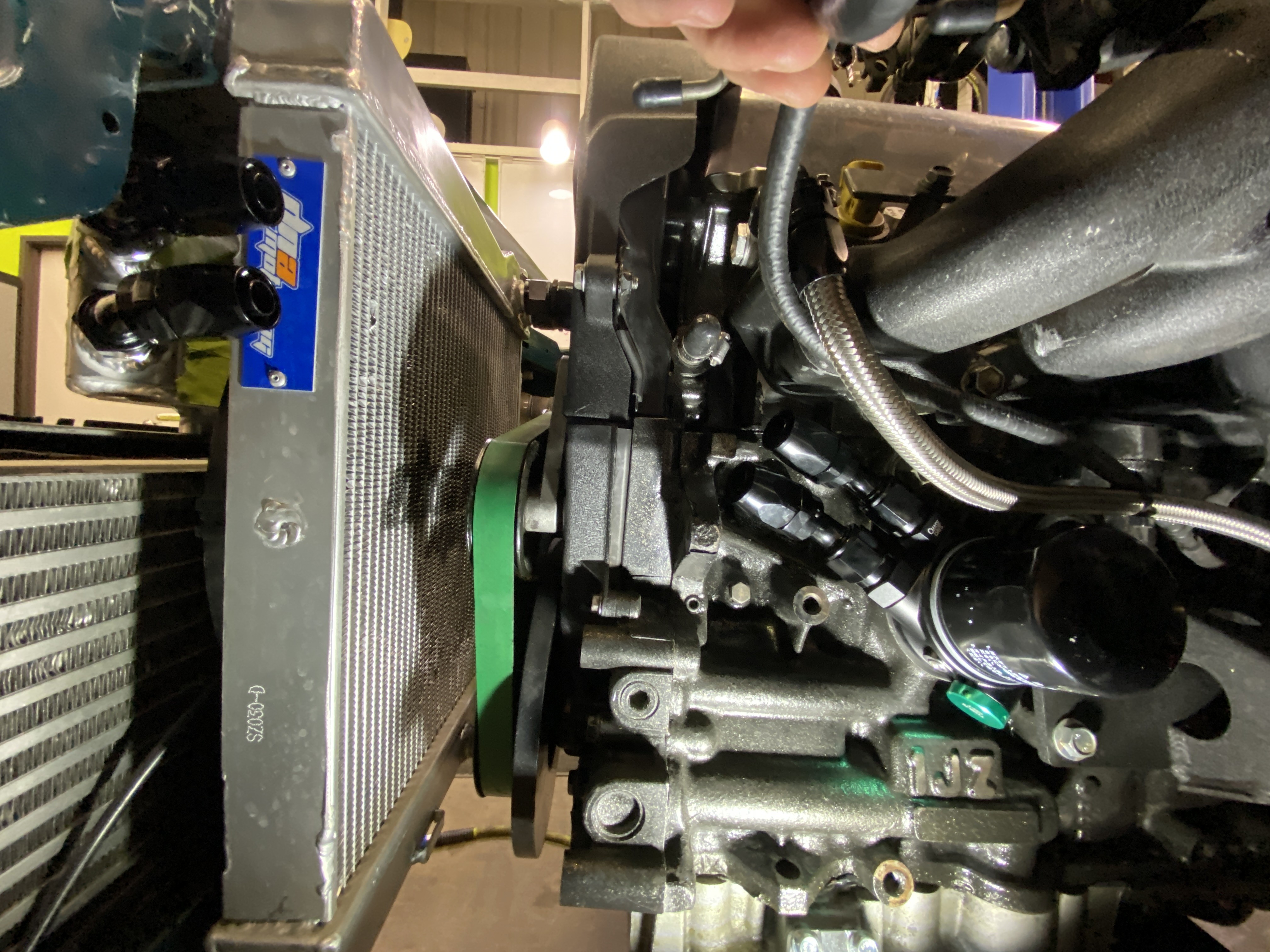
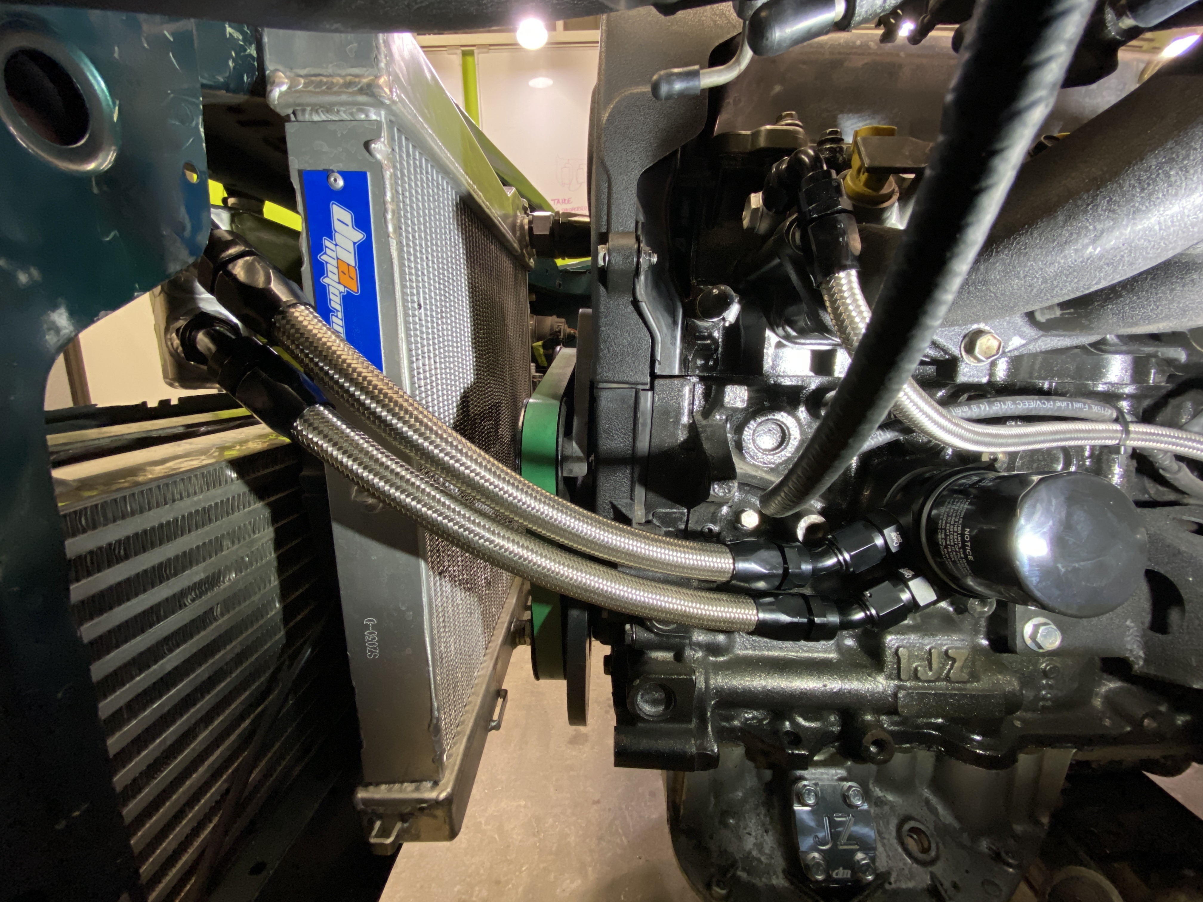
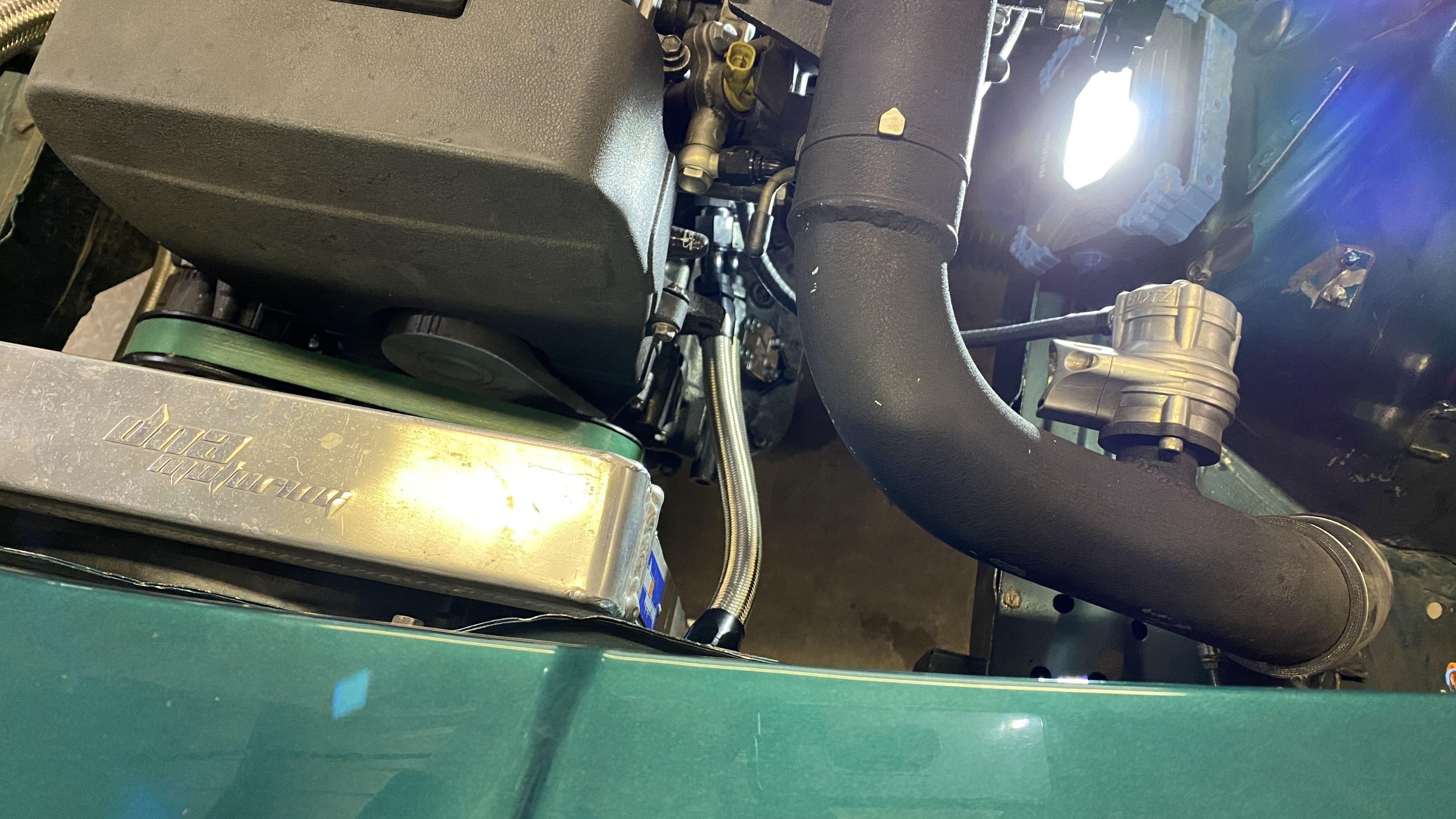
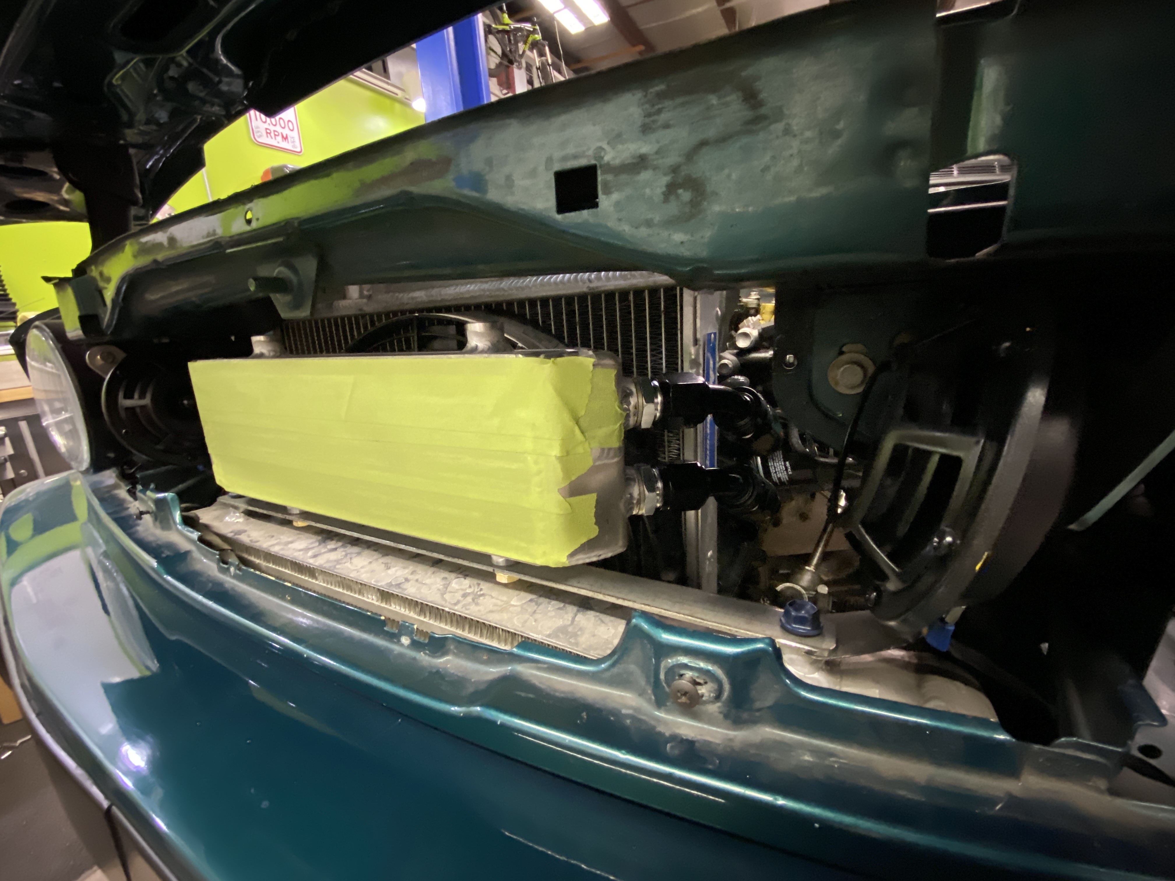
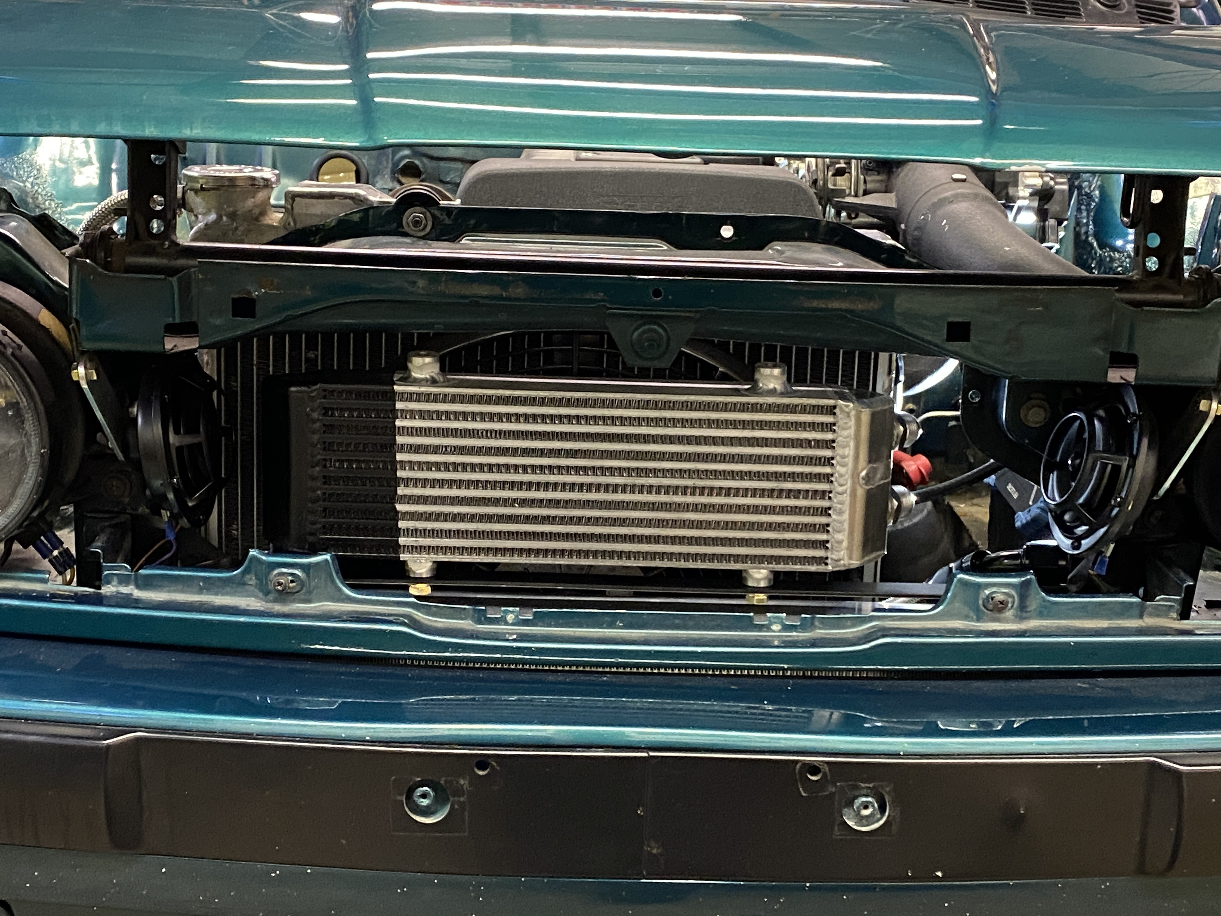
I also ordered everything needed for the remote oil cooler. I got a Chase Bays thermostatic oil cooler wedge plate, HKS filter, -10 fittings (x2 45's| x2 60's), way too much -10 braided line, and I had a cooler that Chubs made a few years ago. I was debating on the line routing, but after I made the lines, it seems like both options I was considering will work if I need to move the lines up in the future.
Option 1
Option 2
The result
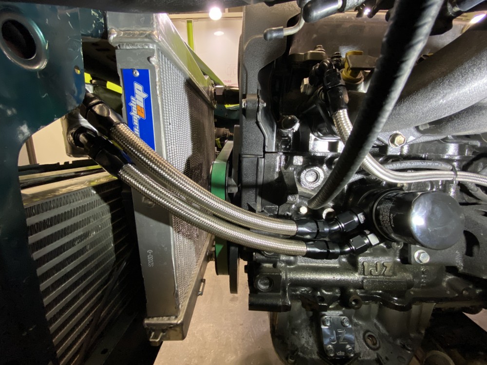
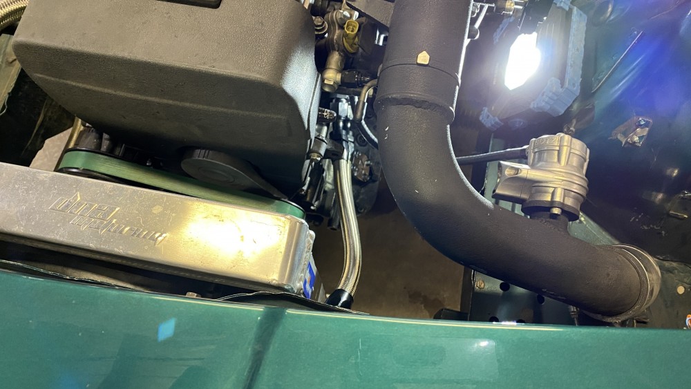
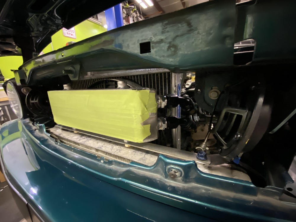
And I also painted the far edge of the oil cooler as I didn't want the offset of the cooler to throw off the factory look of the car through the kidneys.
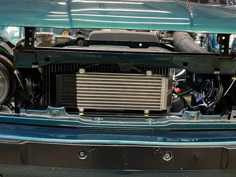
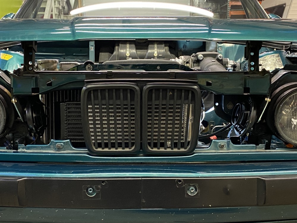
Also not shown, I installed a new oil pan as the one I had was dented since I got it. With that, I also started to reroute my dipstick as it is one of the biggest sys sores in the engine bay IMO. I got about 90% done making a new dipstick, and wasn't sold on how it looked, so I ordered a Lokar locking flexible billet dipstick that I will mount down near the cooler oil filter and out of the way. Besides that, I feel pretty good and the oil system is all buttoned back up!
My next task is going to install the stereo and get that out of the way. I have everything besides drivers and I want to get all the chassis side of the wiring complete before( warning: procrastination excuse) I move onto the engine harness.
https://www.instagram.com/_jdesigner_/ http://nevertoolow.tumblr.com/
🥳SOLD BMW E24 633CSI - BMW M30B32 🧪SOLD HCH ES9 - 1.3 LDA
👽BMW E30 325IC - Toyota 1JZ-GTE ⏰ HONDA EF9 CIVIC SI - JDM B18C5
☠️BMW E36 318i - Ford 5.0 FE302 🚴♂️ GT-Labomba - 26x2.75 Freeride
🤹♀️SOLD BMW E36/7 Z3 - BMW M54B25 🧓SOLD BMW E10 2002 - BMW M10M05 -
It's things like painting the edge of the oil cooler to maintain visual symmetry that I love.
Looking good! -
It's things like painting the edge of the oil cooler to maintain visual symmetry that I love.
Looking good!Thanks! Its hard for me to keep looking at everything in a "temporary" sense as I just want to get it all built, but at the same time I'm so distracted by such minimal details. I really just want to be at the testing / finalizing phase so I can tear it all back apart for the 3 P's; paint, powdercoat, and plating.
https://www.instagram.com/_jdesigner_/ http://nevertoolow.tumblr.com/
🥳SOLD BMW E24 633CSI - BMW M30B32 🧪SOLD HCH ES9 - 1.3 LDA
👽BMW E30 325IC - Toyota 1JZ-GTE ⏰ HONDA EF9 CIVIC SI - JDM B18C5
☠️BMW E36 318i - Ford 5.0 FE302 🚴♂️ GT-Labomba - 26x2.75 Freeride
🤹♀️SOLD BMW E36/7 Z3 - BMW M54B25 🧓SOLD BMW E10 2002 - BMW M10M05 -
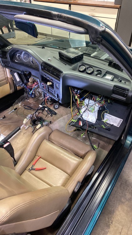
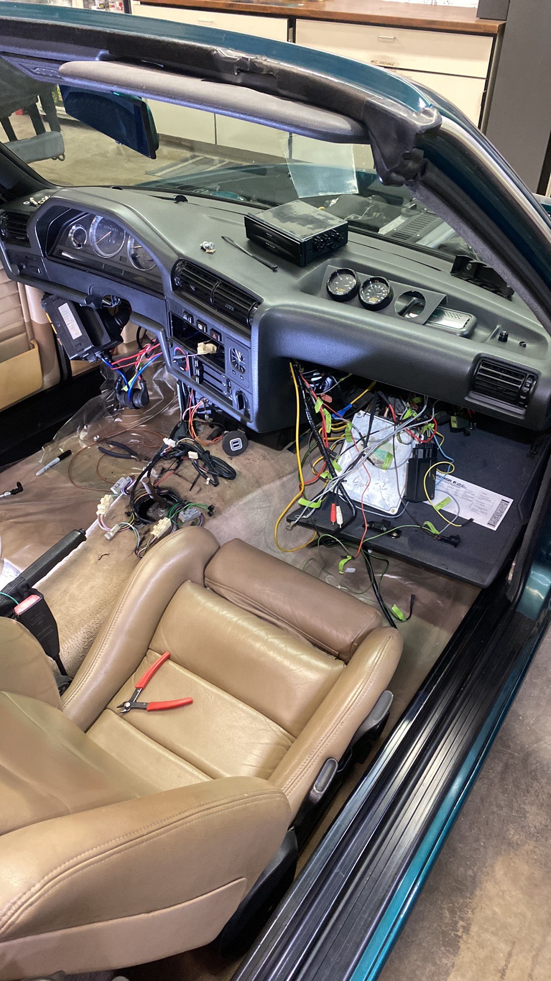
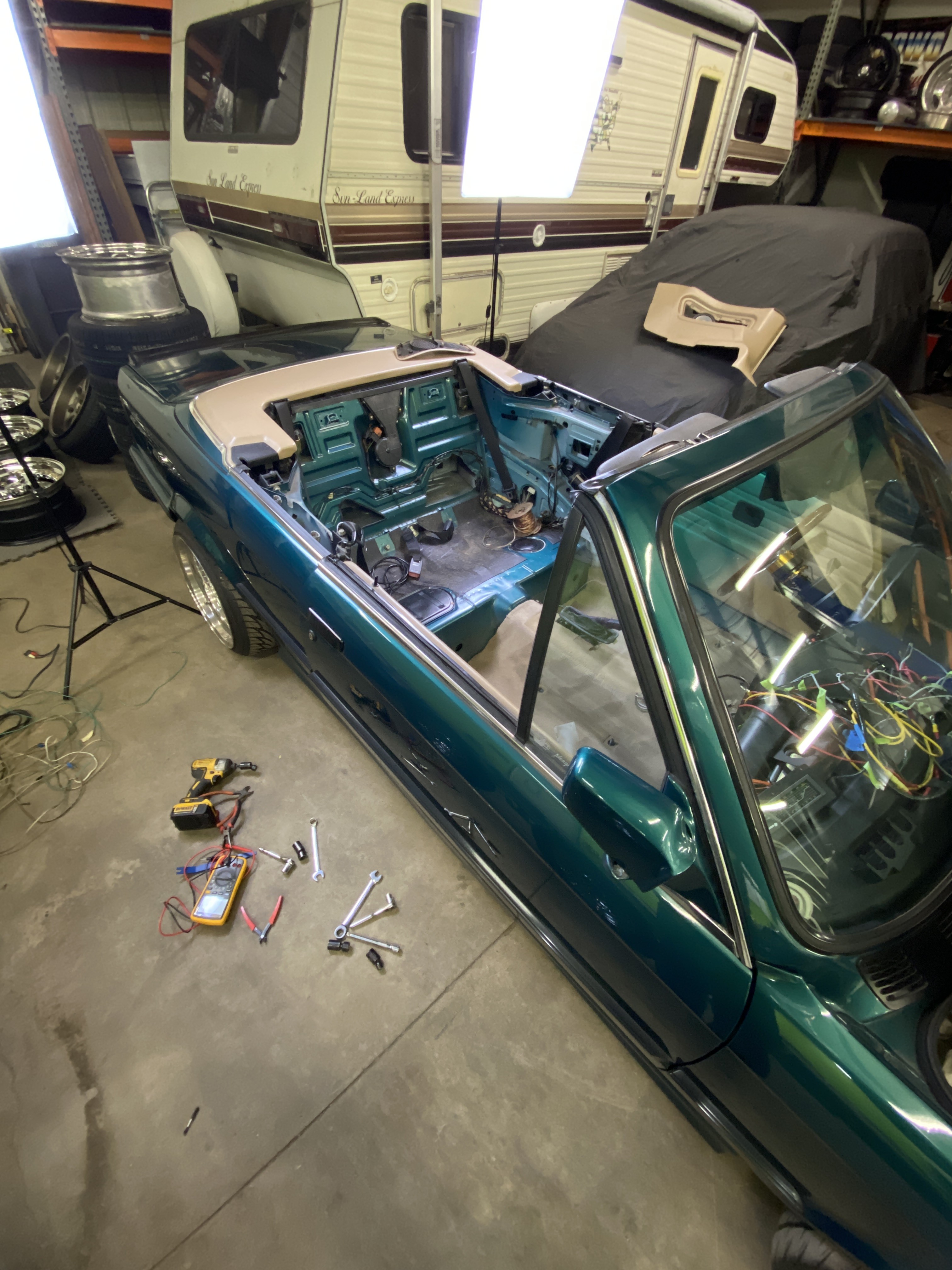
I went a little backwards a few days ago and tore out most of the interior. I was hesitant but it kind of needed to be done sooner or later. I really want to pull the carpet, but that might be too far at this stage. The plan was to hunt down the factory speaker wires and remove them due to the car having premium sound, and upgrade to standard +/- speaker wire that all heads to the back seat of the car. I managed to remove everything needed and cleaned up unused wires for who knows what previously.
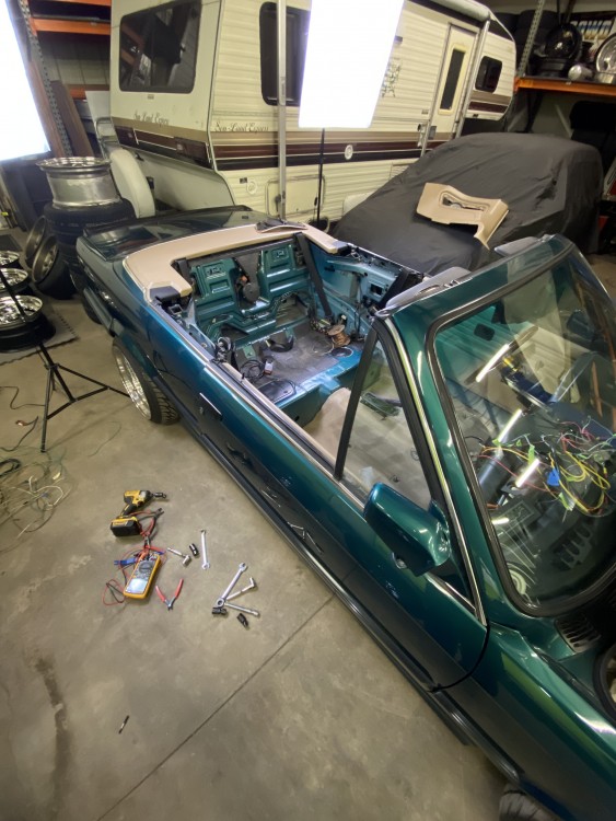
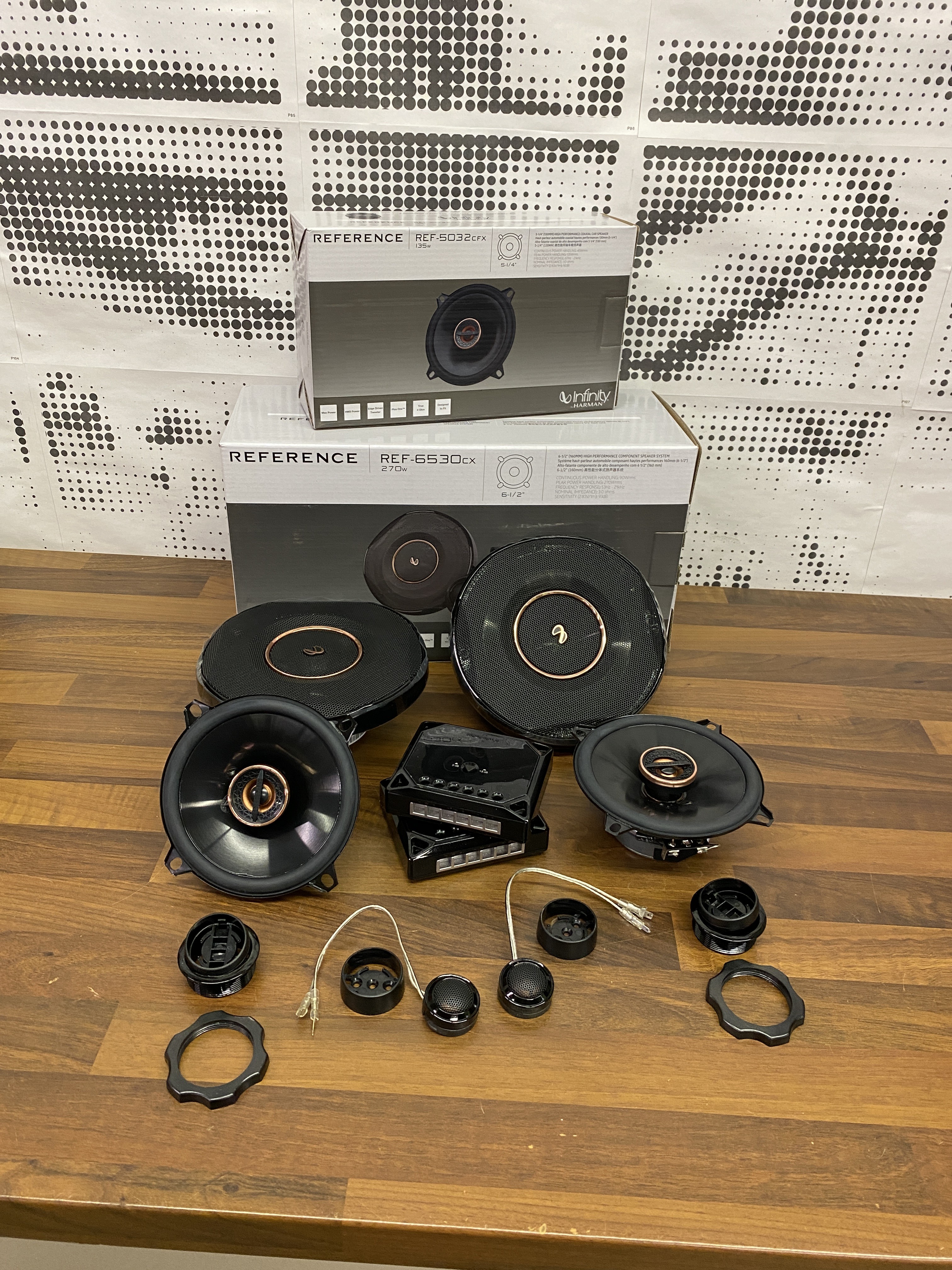
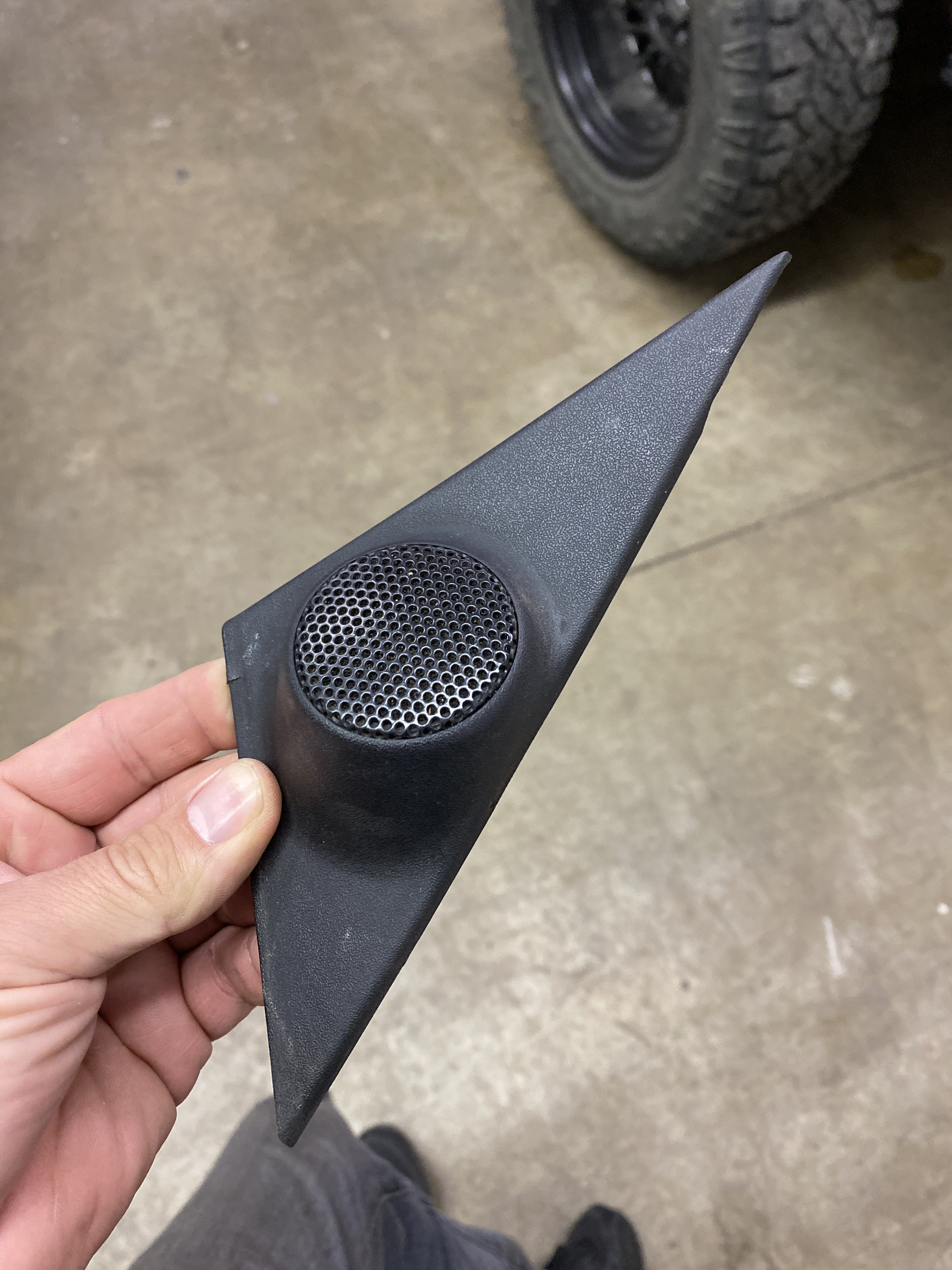
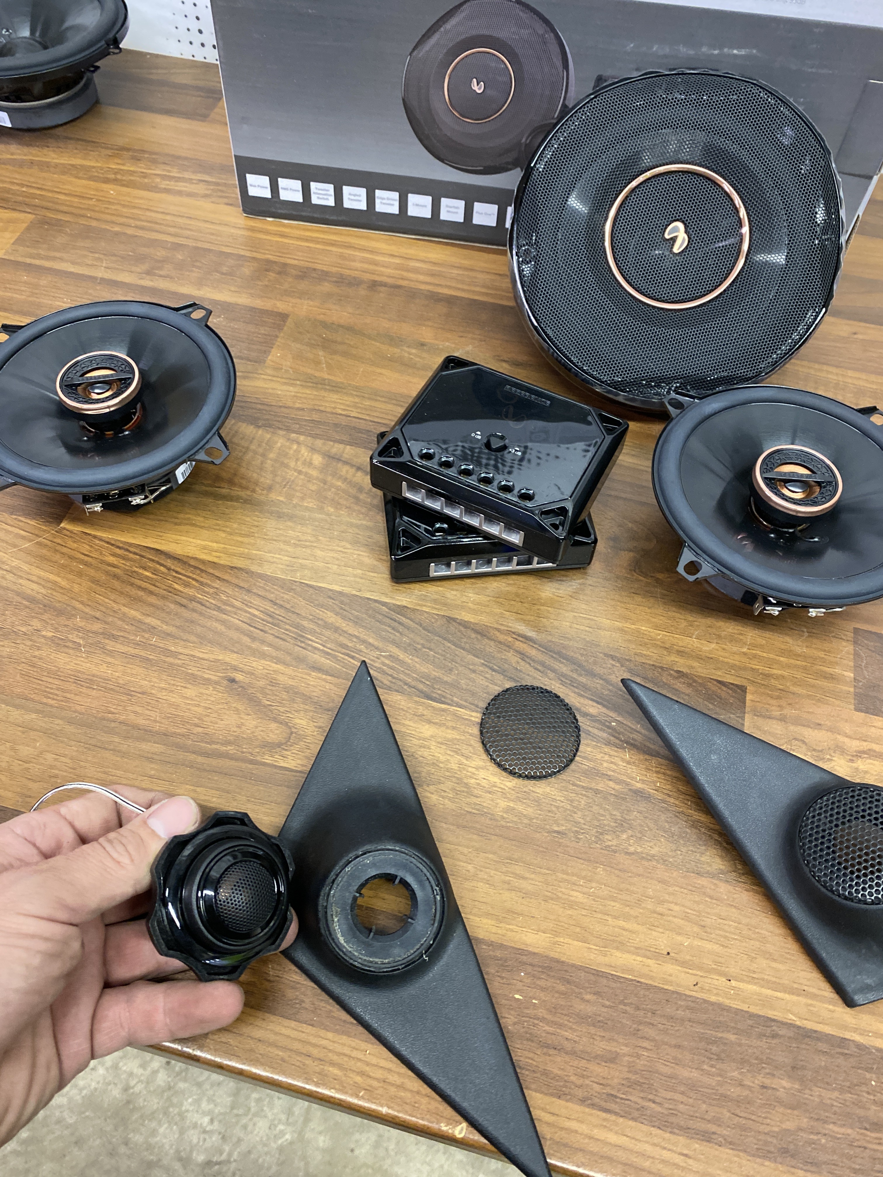
I ordered a full Infiniti reference component set to replace all the speakers and tweeters. Man I had no idea the factory tweeter housings were so expensive for what they are ($150 a side!?) I carefully removed the old tweeter which was glued in really well and mocked up the new ones. Sadly as I was about to trim the housing my rotary tool died, so I ordered a new one and didn't get to finish last night.
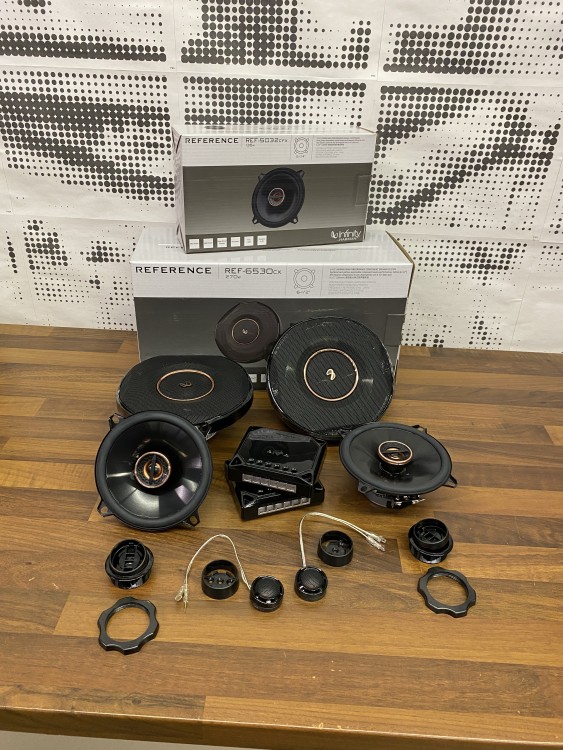
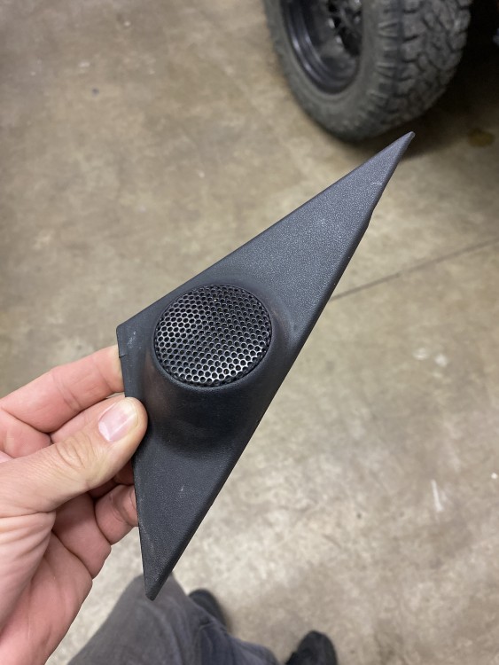
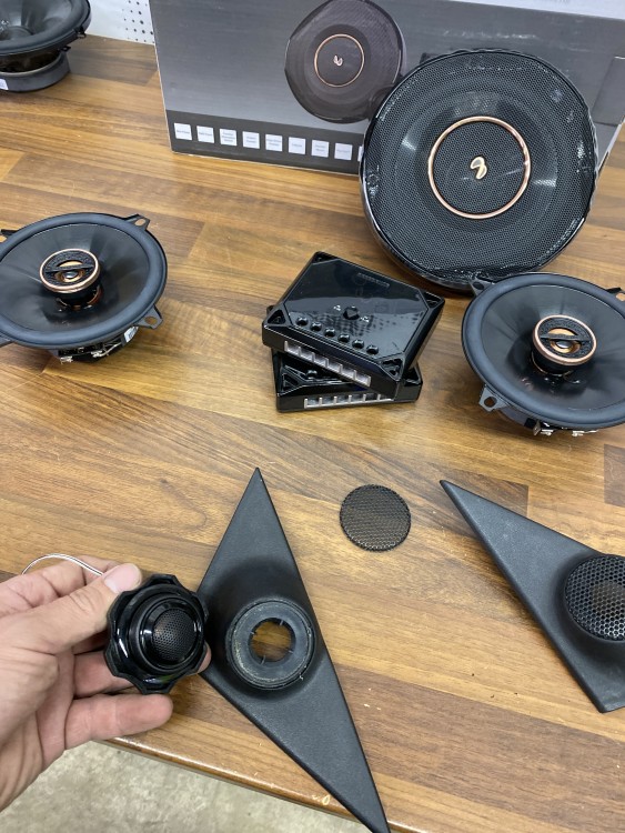
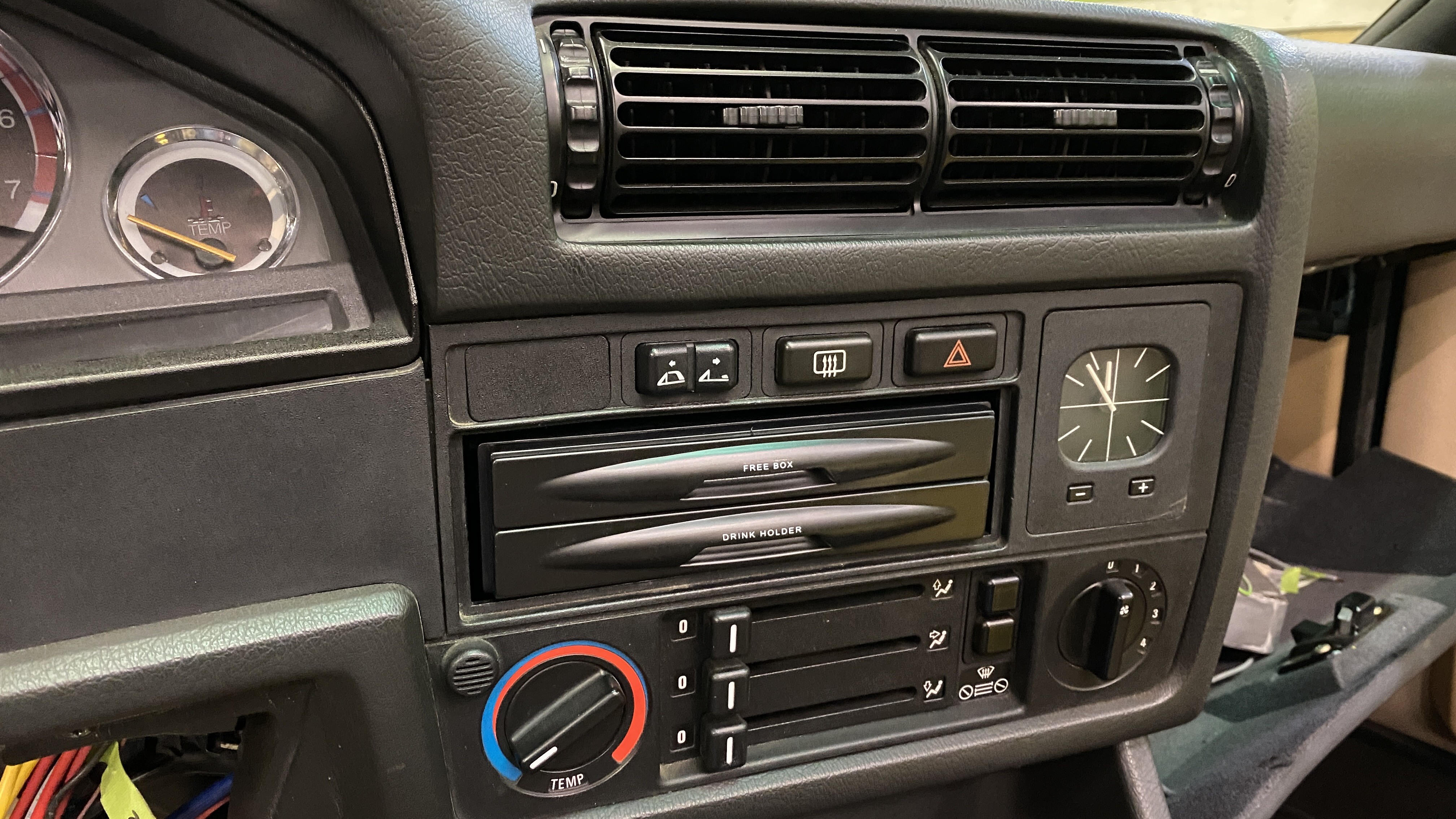
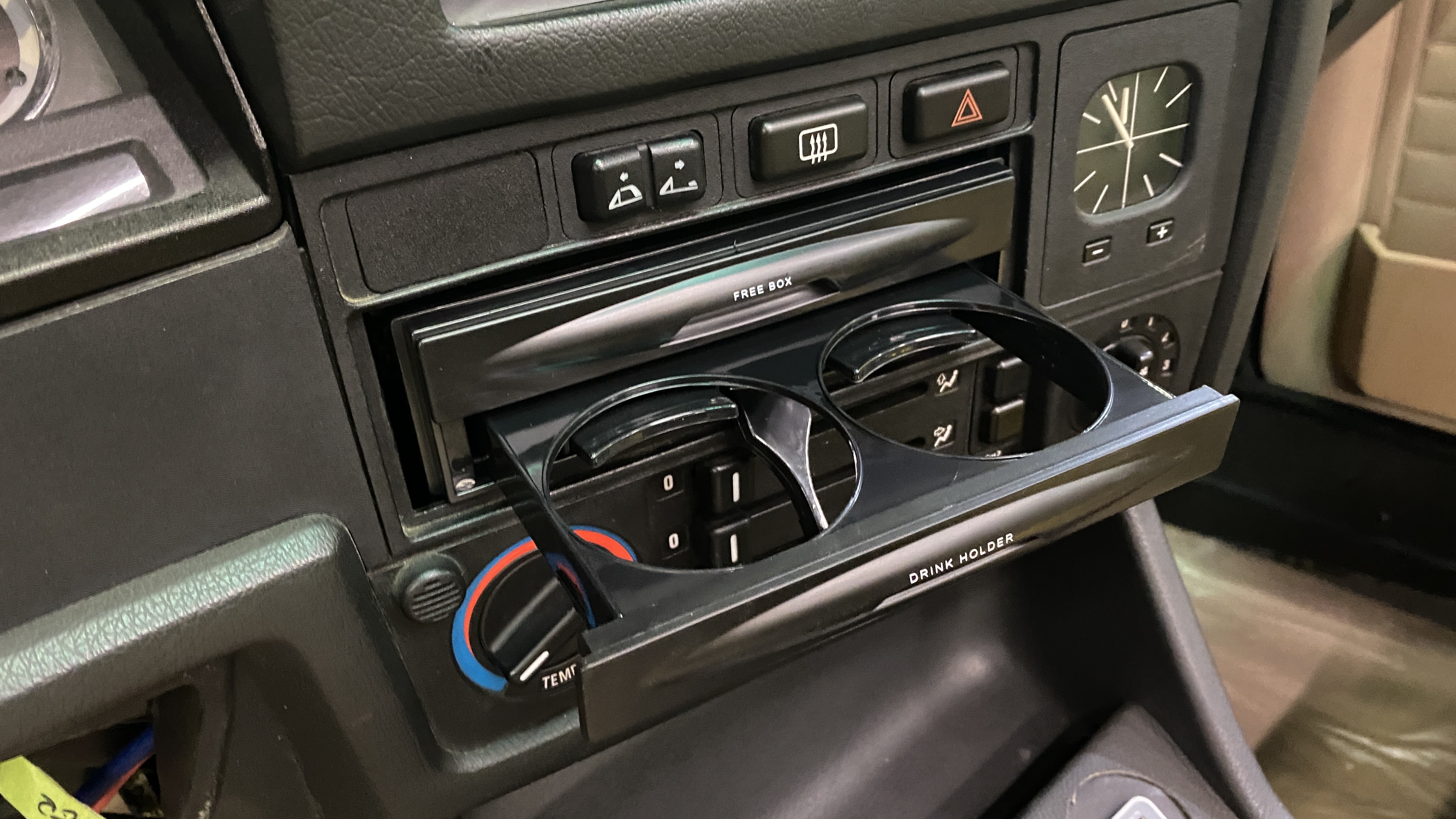
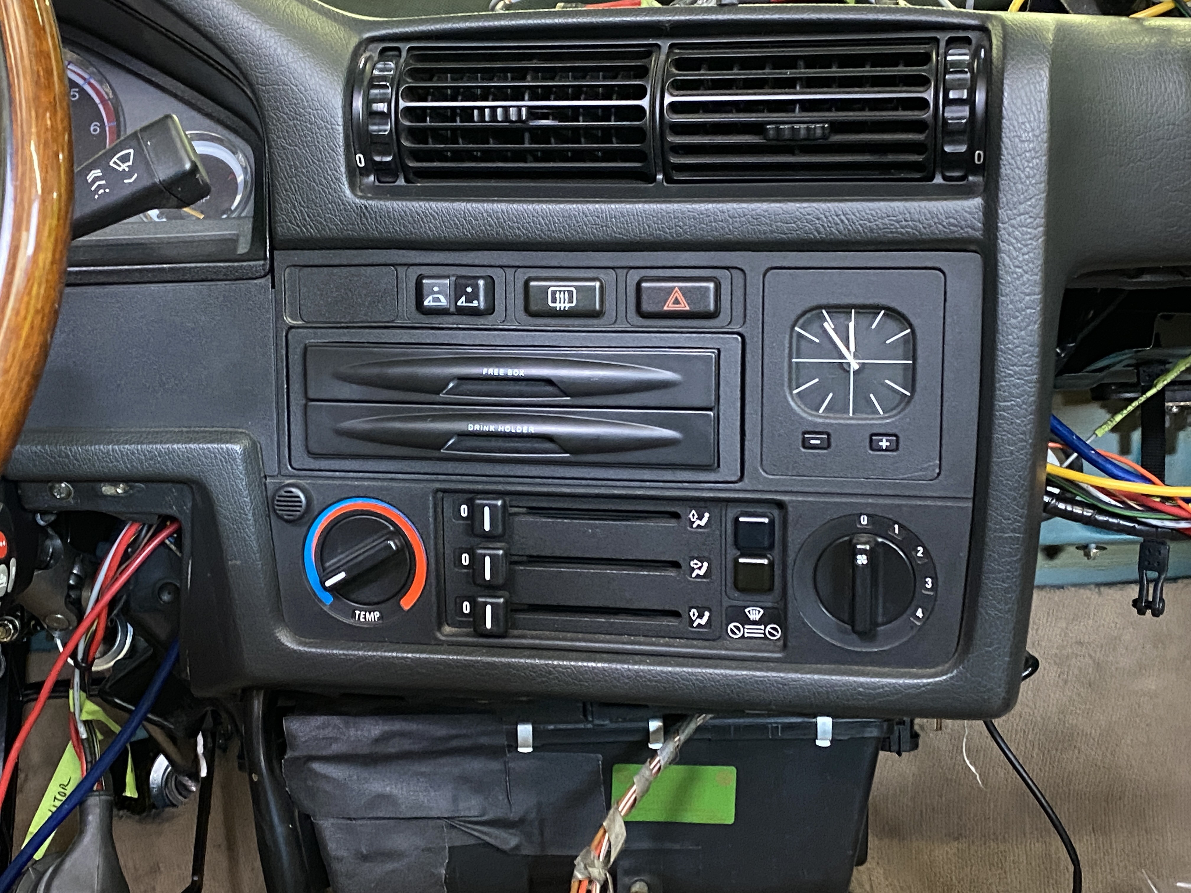
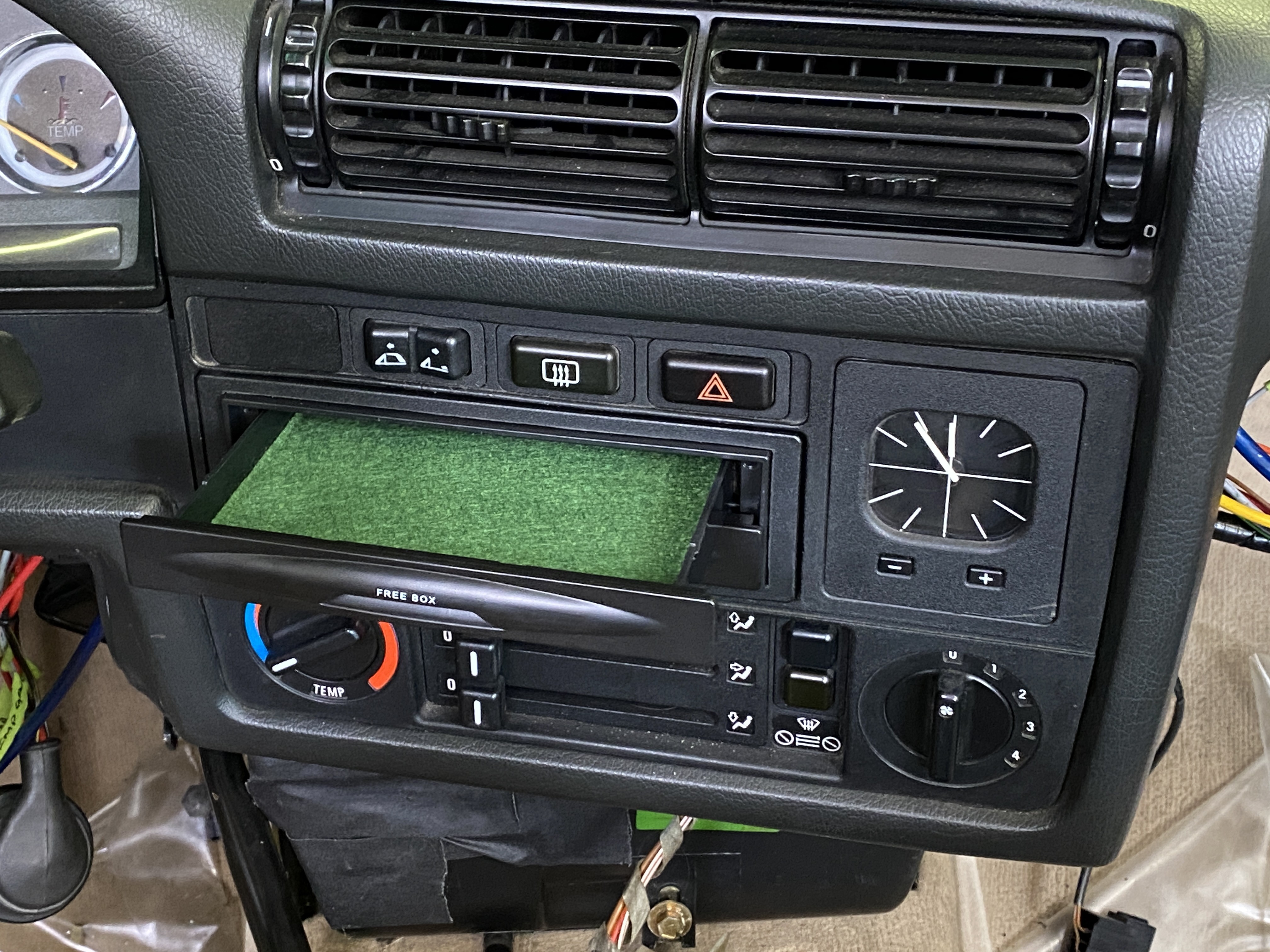
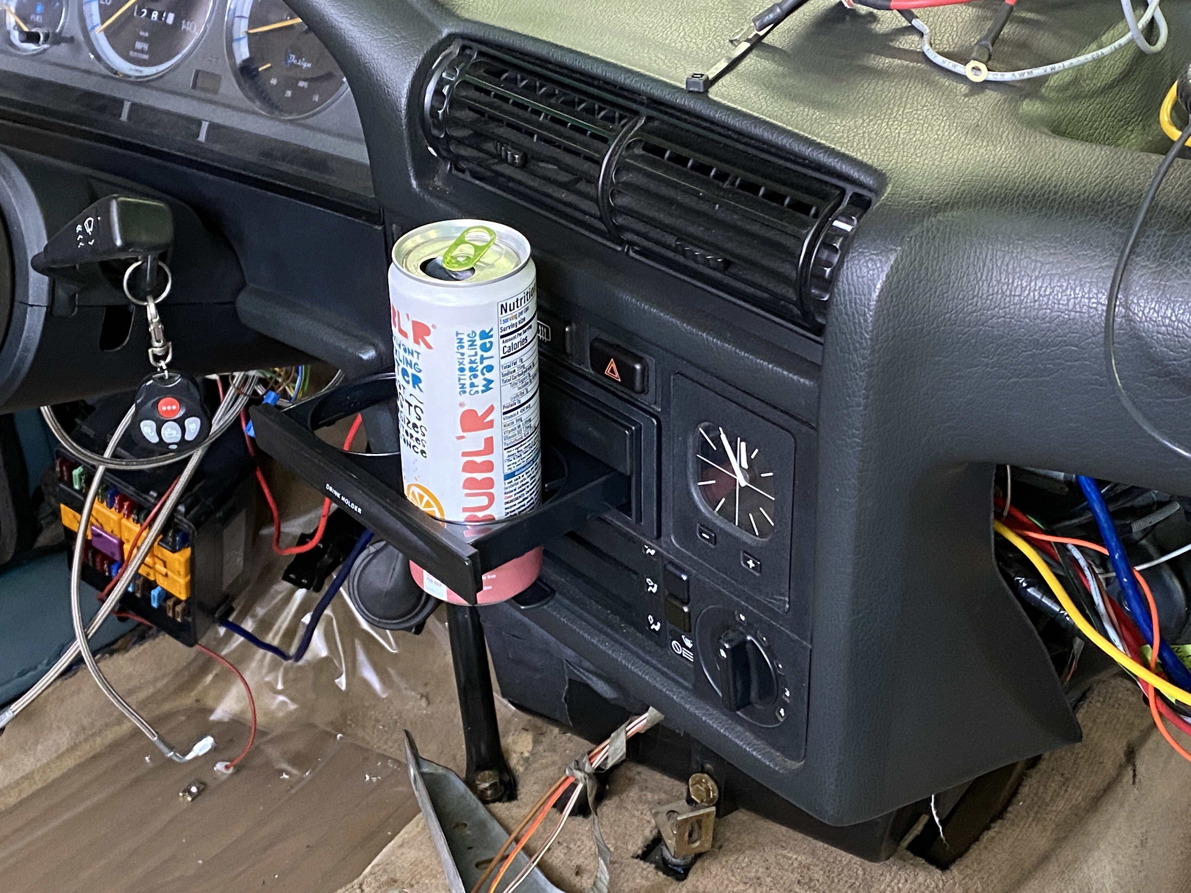
I moved onto the head unit area which I think I mentioned before, but I will not be running a head unit, as my amp connects directly to my phone. So I ordered a single din storage tray/ dual cup holder combo to fit in its place. This was the only one I could find that I knew would fit and wasn't overly complicated. I wasn't please with the quality as it felt cheap and the trays pulled out loosely and uneven as there are no guides/ slides for the drawers. I fixed this by adding felt to the inside edges of the drawers which completely changed the feeling of them. This made such a huge difference. I also added some green felt inside the drawer to class it up a bit.
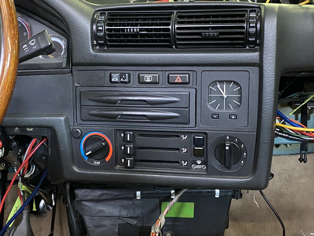
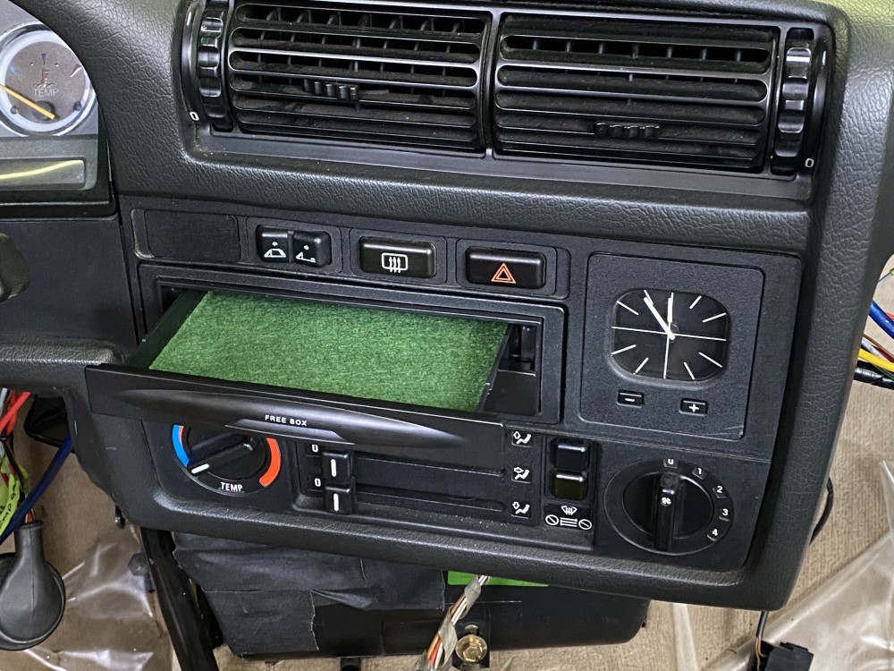
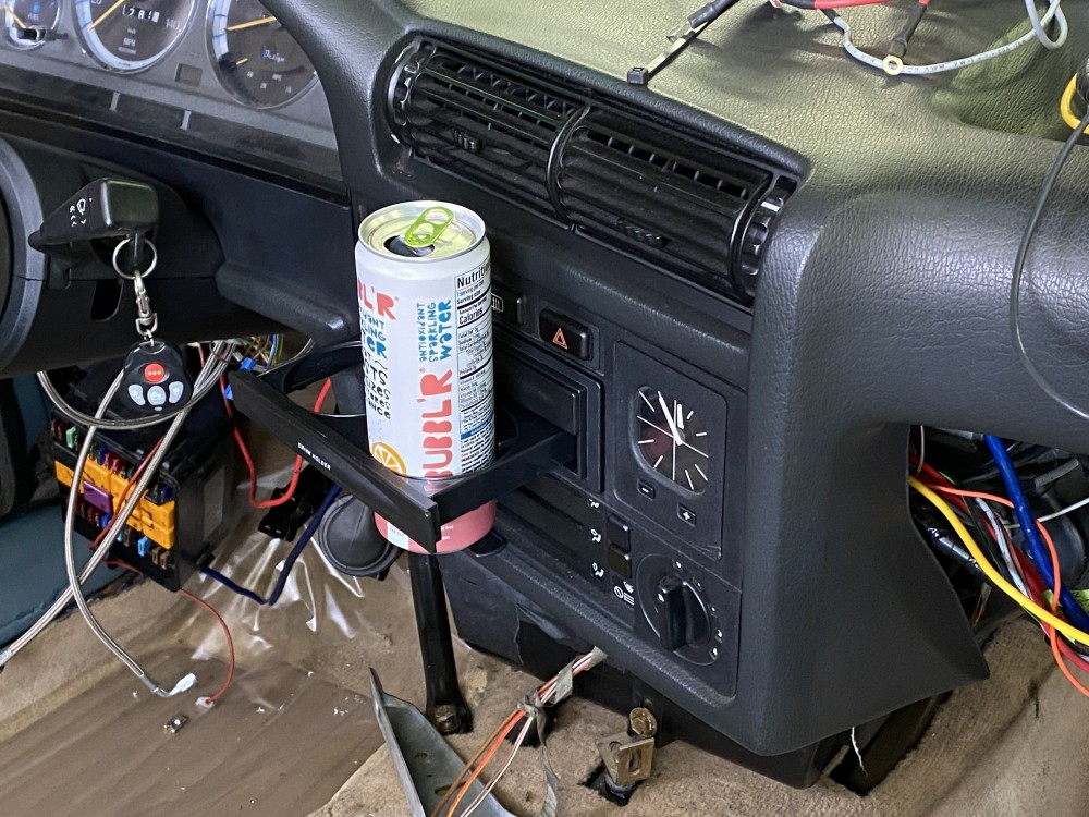
That's all for now until I finish the tweeters and get the amp mounted. I plan on building an enclosure in the void between the rear seat and the trunk for a sub eventually, but for now this is a huge improvement.
https://www.instagram.com/_jdesigner_/ http://nevertoolow.tumblr.com/
🥳SOLD BMW E24 633CSI - BMW M30B32 🧪SOLD HCH ES9 - 1.3 LDA
👽BMW E30 325IC - Toyota 1JZ-GTE ⏰ HONDA EF9 CIVIC SI - JDM B18C5
☠️BMW E36 318i - Ford 5.0 FE302 🚴♂️ GT-Labomba - 26x2.75 Freeride
🤹♀️SOLD BMW E36/7 Z3 - BMW M54B25 🧓SOLD BMW E10 2002 - BMW M10M05

Hello! It looks like you're interested in this conversation, but you don't have an account yet.
Getting fed up of having to scroll through the same posts each visit? When you register for an account, you'll always come back to exactly where you were before, and choose to be notified of new replies (either via email, or push notification). You'll also be able to save bookmarks and upvote posts to show your appreciation to other community members.
With your input, this post could be even better 💗
Register Login