
TehRaydarlover's AWD lover

-
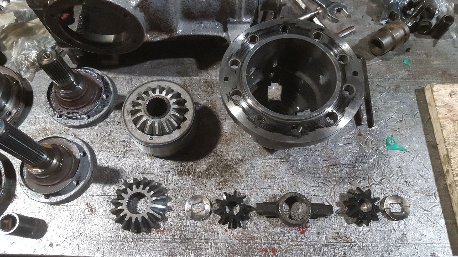
So now with everything in the carrier taken apart I just looked for any abnormal wear on the gears and shims. I did notice a small gall on one of the spider gears. I took some 600 grit sand paper and polished the high spots out. With everything else looking good we can reassemble the carrier just as it came apart. Before bolting on the end cover, you should stone the mating faces to remove any high spots or dings from rolling around on your work bench. You will see me stoning faces a lot coming up, it’s really critical that this is done to avoid any sort of misalignment that will show up in your gear mesh pattern ultimately reducing the life of the diff.
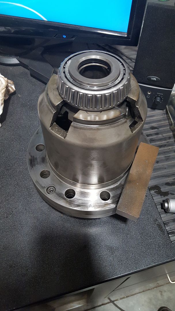
Next we can reinstall the crown gear. Again you should stone both of the mating faces. You are going to have to chase the threads in the crown gear. BMW used a thread locker and you need to clean it out before reinstalling.
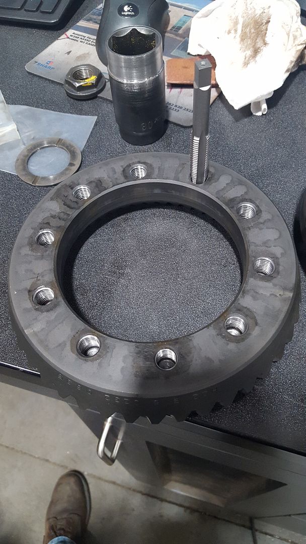
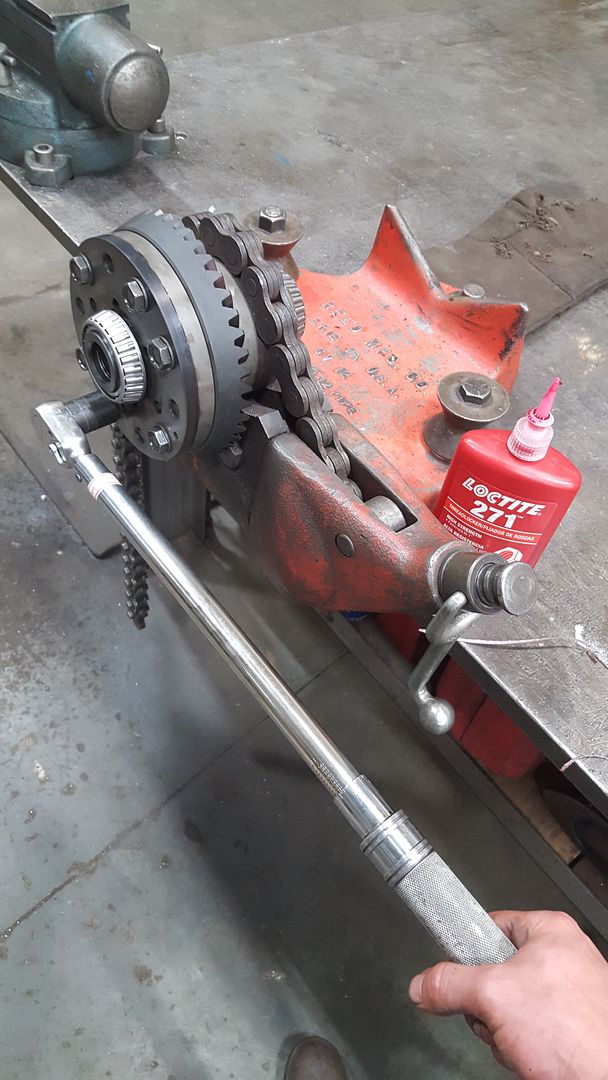
With everything clean we can bolt the crown gear on. Because the crown gear is a slight interference fit to the carrier just install 4 old bolts and use an impact alternating bolts until the gear is fully seated on the carrier. Then you can juice up all of the new bolts with Loctite and hand tighten them, BMW does spec out to replace these. The crown gear bolts are torqued to 140 ft-lbs. I did one pass at 100 ft-lbs then a final pass at 140 ft-lbs.
Now it’s time to remove the old bearings and press on the new ones. You might be able to get the bearings cages and inner races off with a large 3 jaw puller, but I ended up using a clam puller and a hydraulic jack.
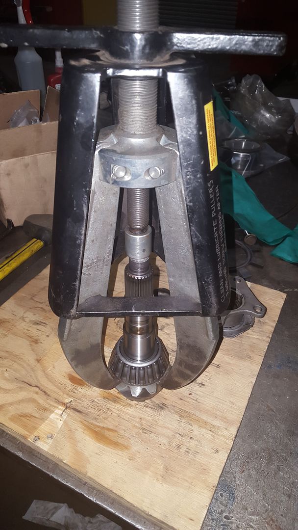
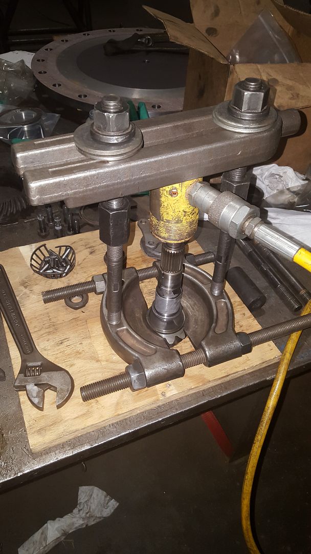
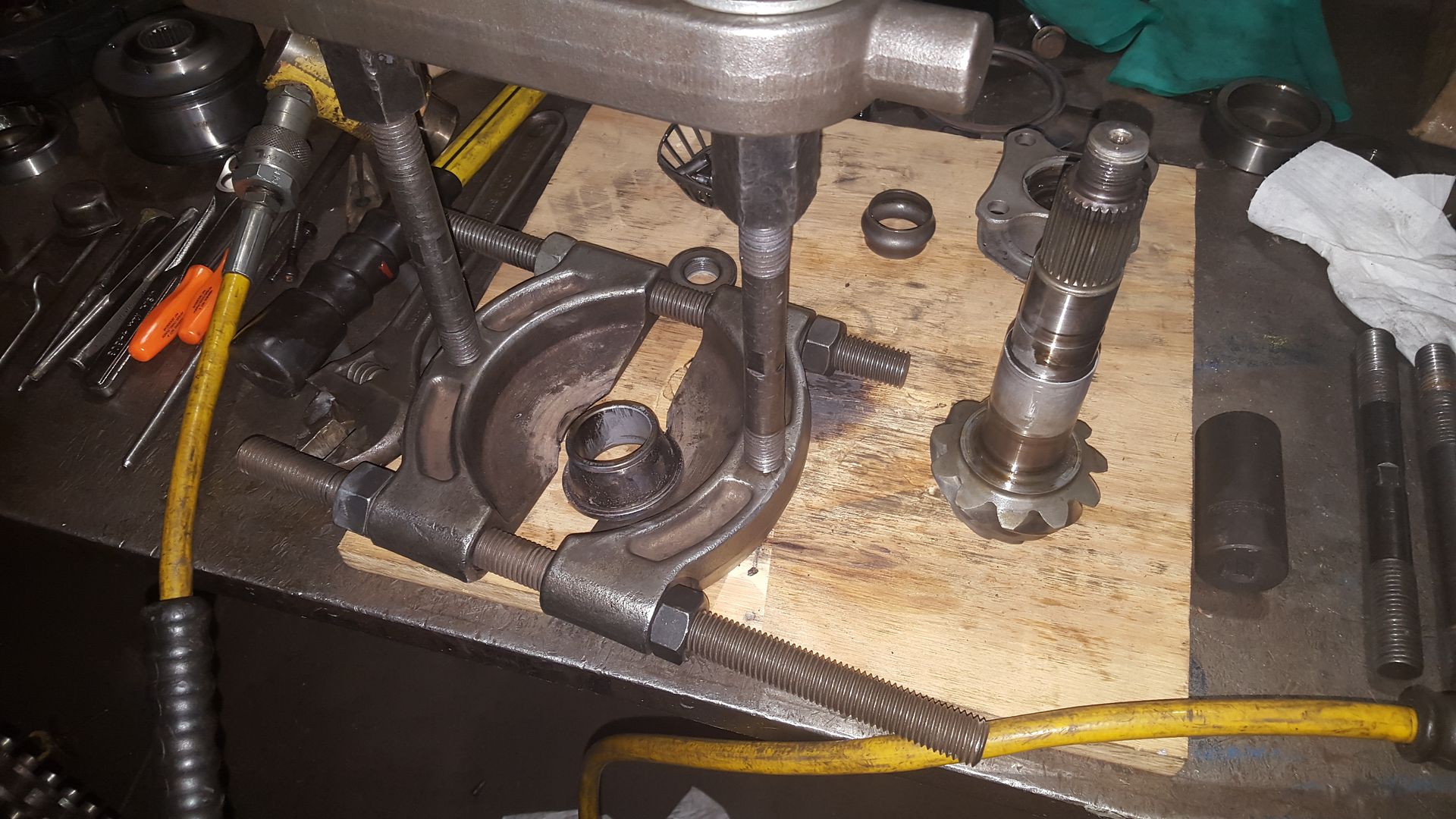
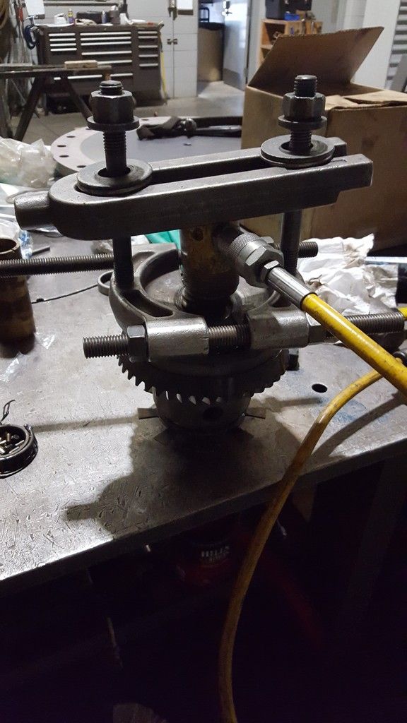
To get the outer races out of the carrier flanges and casing you’ll need to a hunk of metal with a slightly smaller diameter and either beat them out with a hammer or with a press. Be careful when you press out the races out of the casing as there is a shim under the inner bearing that you NEED, DON’T LOOSE IT haha. It would be a huge pain to try and recalculate the required thickness. The shaft seals can also come out of the carrier flanges.
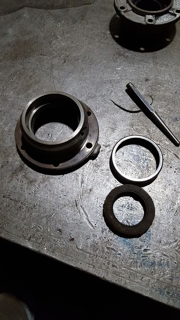
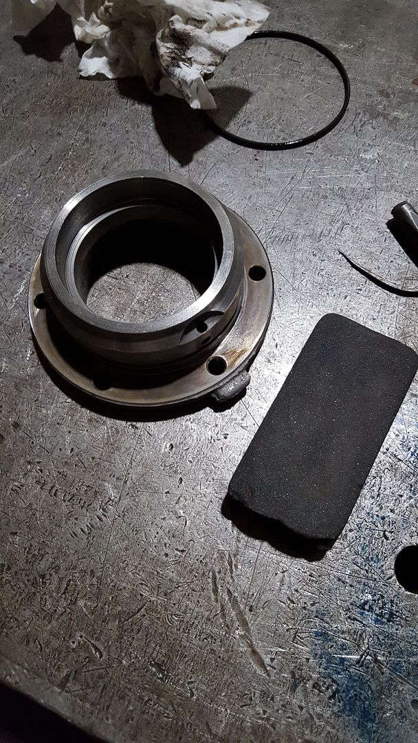
Once you have the outer races removed take them over to the belt sander and take enough material off of the OD that you can freely slip it in and out of its receiving bore. We’ll use these to reinstall the new outer races. With the outer races removed you can do any final cleaning of the casing and carrier flanges. My carrier flanges had some left over corrosion outside of the shaft seal that I cleaned up so I didn’t damage the new seals during installation. I gave the receiving bores a LIGHT coat of RTV and tapped the new shaft seals in with another piece of metal with a slightly smaller OD.
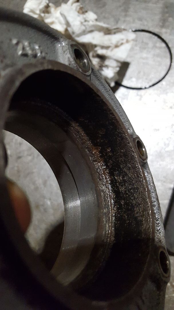
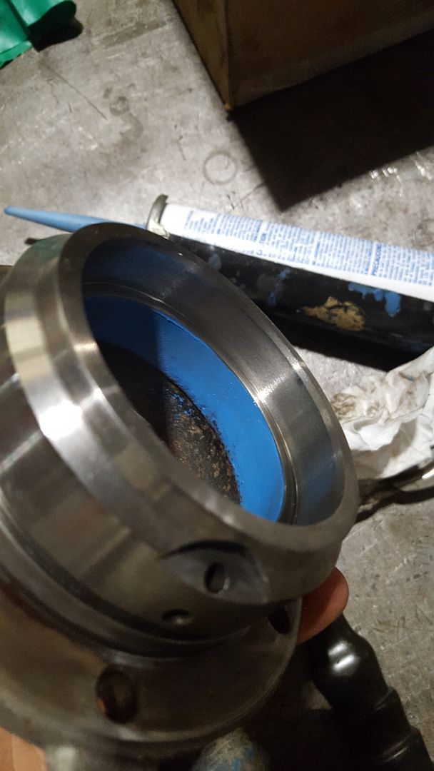
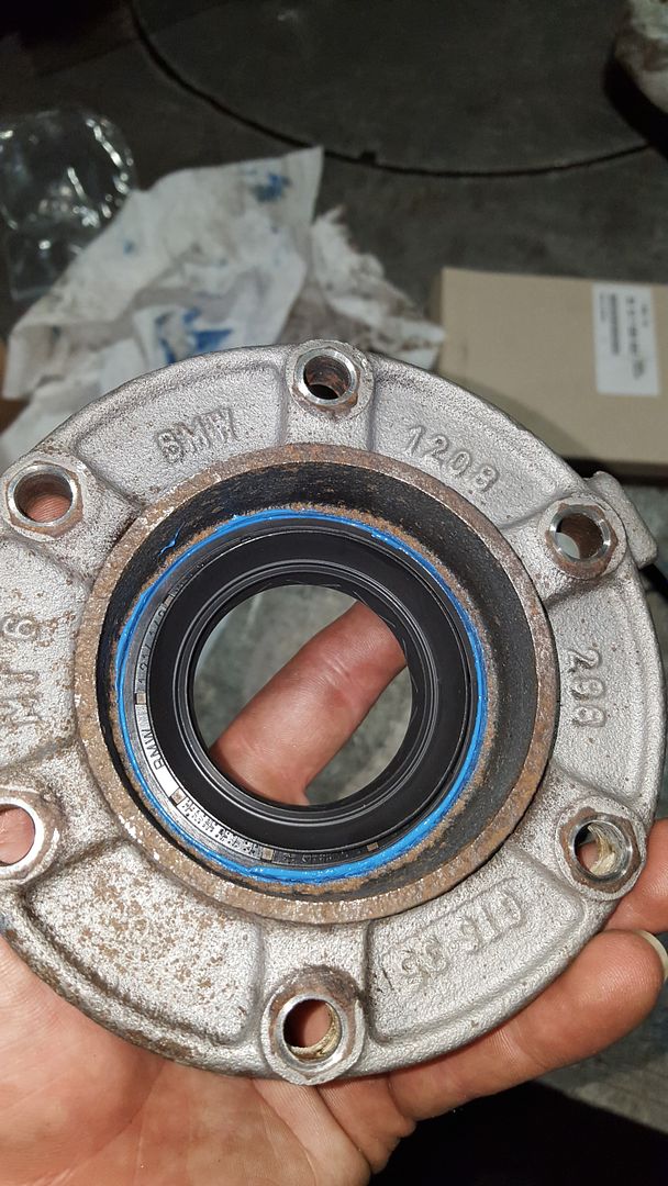
After giving the receiving bore a coat of oil it’s time to press in the new outer races. Try and get the new race started as straight as you can in the receiving bore. Then set your old race with the sanded OD on top of it and press it home.
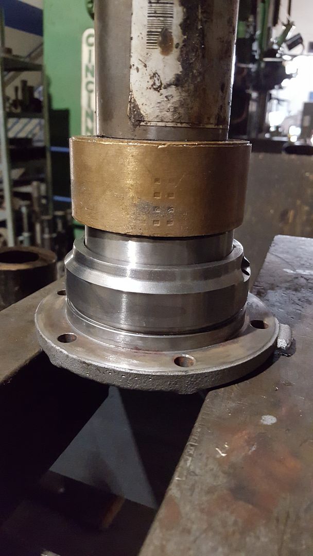
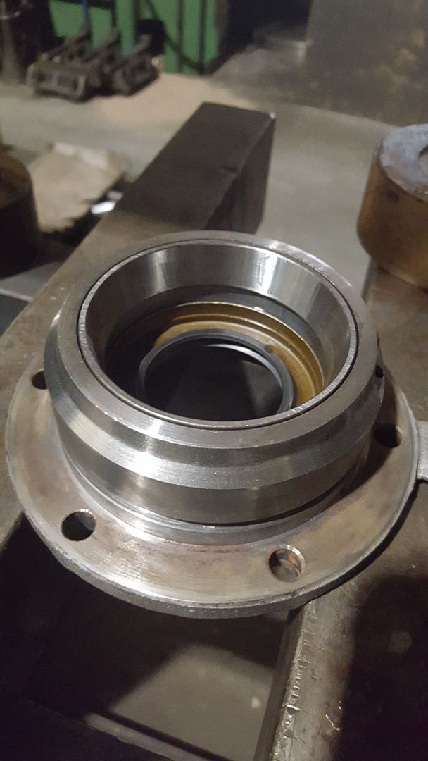
Do this also for the outer races that go into the casing. Remember to put the shim back behind the inner bearing’s outer race.
-
Alright now were ready to start final assembly. First we are going to set the preload for the carrier bearings. This is done by altering the combined shim thickness for the two shims that go between the carrier flanges and the casing. Hopefully you kept the old ones that came out of the diff when you disassembled it as they should be relatively close to what it needs to be. If not BMW sell shim packs that are stepped in two thou increments. My original shims measured 0.0XX” for the driver’s side and 0.0XX” for the passenger’s side, with a total of 0.XXX”
The first step is to stone all of the mating surfaces of any high spots or corrosion build up. This includes both sides of the shims, the carrier flange faces, and the casing faces. We really want to make sure these are clean because even a little bit of crud will mess with your preload.
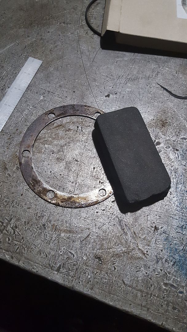
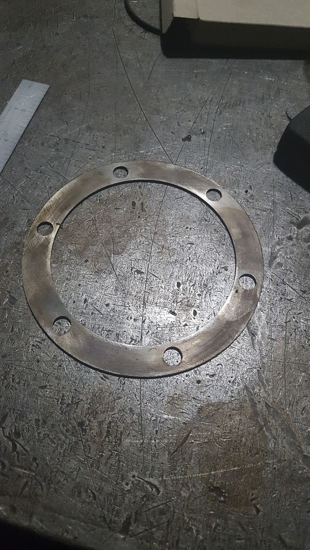
We’re going to start with the original shims and go from there. Install the carrier with the two shims. Torque the carrier flange bolts to 17 ft-lb. Then we are going to measure the rolling torque, you are going to need a beam style in-lb torque wrench. To measure the rolling torque, I took the longer output shaft and installed it partially into the carrier. You want it in enough to engage the splines but not enough that the shaft seal touches the shaft. This ensures we are only measuring the bearing rolling torque and not the drag from the shaft seal. Then I installed a few bolts and used a random bar with a 1/4” square in the center to plug the torque wrench into. This is what I came up with, you can do whatever you want as long as the center of the torque wrench is centered in the flange.
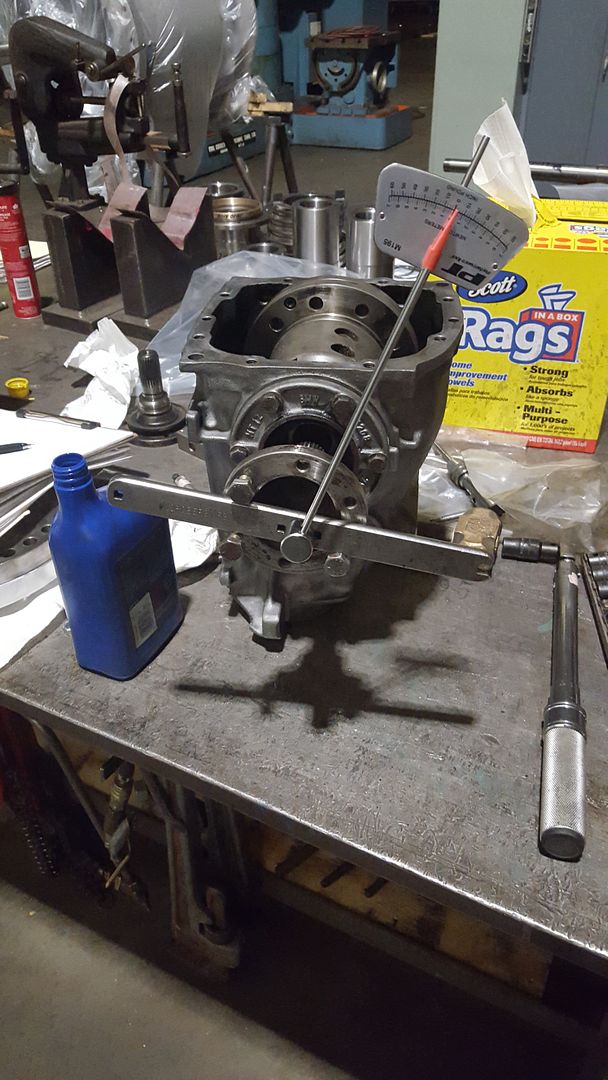
With it set up similar to above you measure the torque required to keep the carrier spinning, “rolling torque”. We are looking for 9-11 in-lb. When I first measured it I had 6 in-lb. Which is too light, this means I need to decrease the combined shim thickness. If you chose to buy the shim pack you can just use the next smallest shim thickness for one side and try again. I did not order the shim pack so I used a surface grinder to skim one of the shims as lightly as possible, test and repeat until I got it within the required range. This has the potential to be very tedious but it needs to be right for the diff to have a long life.
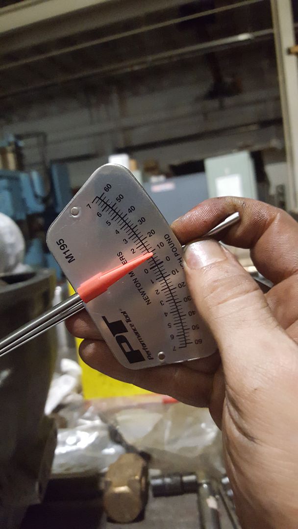
Once you get it within 9-11 in-lb record the total shim thickness of the two shims. Later, to get the correct backlash and tooth pattern we will need to alter the each shim while keeping the total shim thickness the same.
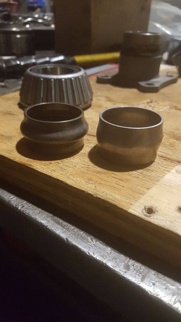
With the carrier bearing preload set we can now install the pinion. This is where the annoying crush bushing comes into play. The way it works is as the bushing crushes the pinion bearing preload or rolling torque increases.
Sorry if I’m a little light on the pictures, at this point it was a long day and I wanted to go home haha. If you want to know anything else about what I did, let me know.
With the pinion placed in position in the casing, you’ll have to find something with the right height to hold the pinion in the casing as you press on the outer bearing. With the pinion held you can slide on the new crush bushing. Next we are going to press on the new outer thrust bearing. You do not want to press it on all the way to the point where you are crushing the bushing. This is just to start it on the pinion shaft. Get it started and press it on little by little until there is about a 1/16” of play. The rest we will do by hand. It should look something like this at this point: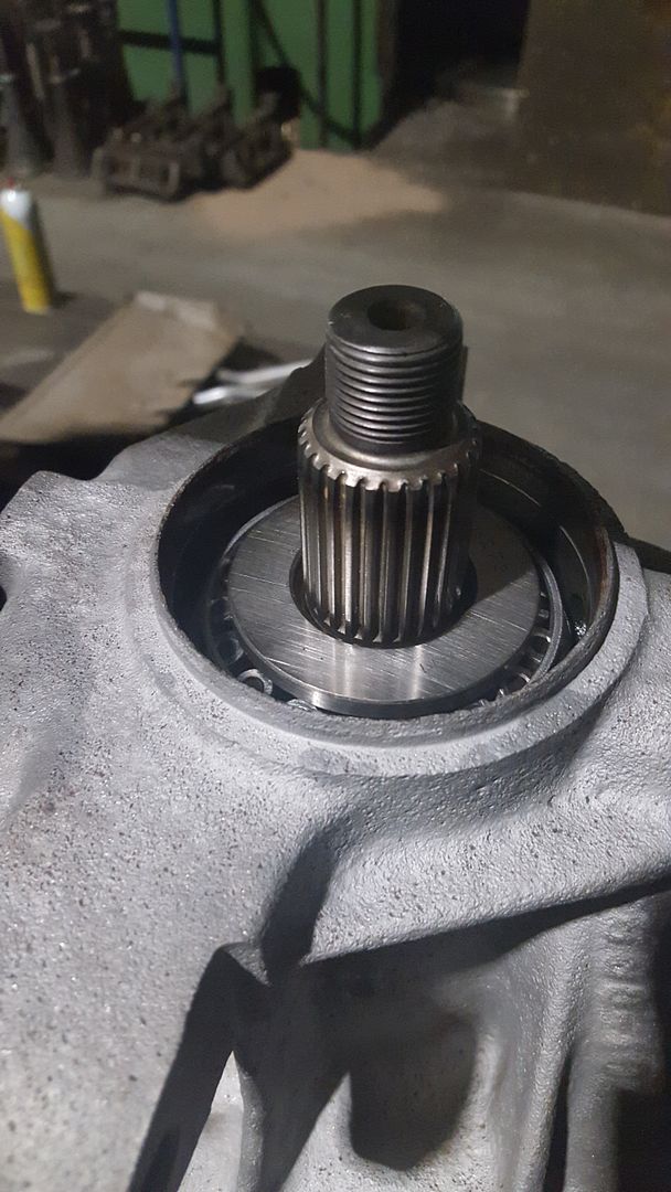
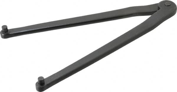
Now you can install the input flange and nut. To tighten the nut and start to crush the bushing you’re going to need something to hold the input flange as you tighten the nut. I used a spanner wrench like this.
As you tighten the nut the bushing will crush and the bearing preload will increase. I came up with a similar setup to measure my rolling torque of the pinion bearings. The range we are looking for is between 15-20 in-lb. With the input flange restrained you can start to tighten the nut with an impact. You really need to take your time and go slow. Put your impact on the lowest setting. If you accidently go too far and have too much of a preload there is no going back, you’ll have to buy a new crush bushing and start over. That being said it’s always a good idea to buy 2 or 3 just in case. As you tighten, measure, and repeat keep an eye on the match marks you made on the nut and input flange when you disassembled the diff. You should be very close to this mark when you’re in the right range. Again take your time and check often When you successfully set the preload you can make another set of match marks on the nut and input flange. . I got mine set at about 17 in-lb. Note: just like the carrier bearings we are doing this without the shaft seal.
This picture was taken after the shaft seal was installed.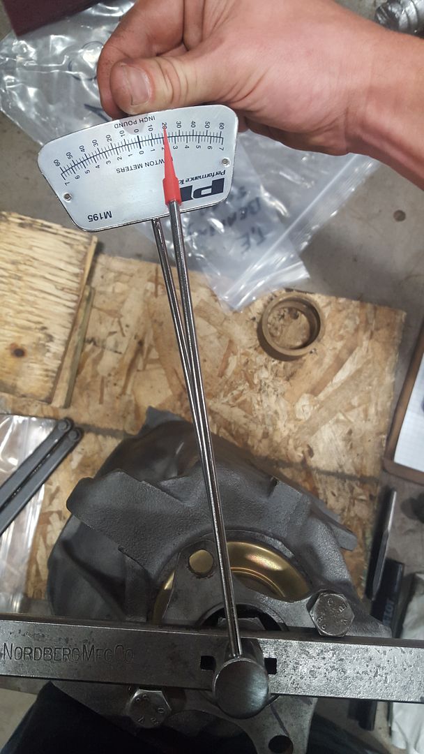
I did find a spec from BMW that the pinion shaft seal add 2 in-lb to the rolling torque. And I verified this with the measurement shown in the picture above, at about 20 in-lb. If you decided you want to do set the preload with the shaft seal installed keep that in mind.
With the nut and input flange marked, you can remove the nut and input flange and install the shaft seal. For this I didn’t use any RTV as I wouldn’t have been able to clean off any excess. I put a light coating of oil on the receiving bore and seal then tapped it in flush with the cover. Also install the new dust cover if you bought one.
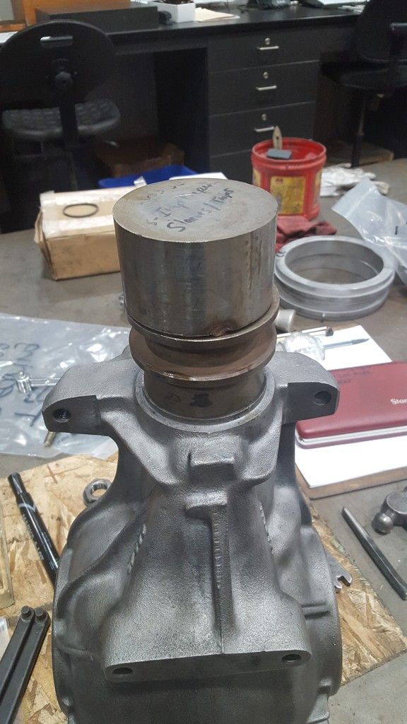
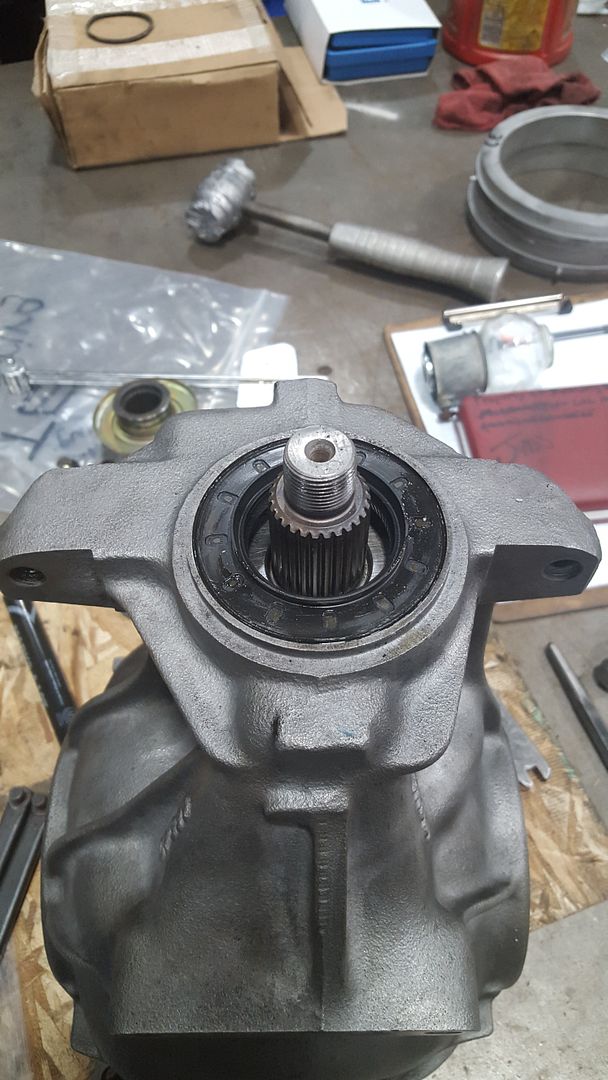
After the shaft seal is installed you can reinstall the input flange tightening the nut to the match marks you made. It should be easier this time as the bushing is already crushed, but again take your time it would be a shame to screw it up now. It’s a good idea as you get close to tighten, measure, repeat until you’re at your mark and there’s about a 2 in-lb increase in your rolling torque.
Alright, scary part done have a beer.
Now with the pinion installed we need to install the carrier with our shims and check our gear tooth pattern and backlash. These are good charts for correcting your gear tooth pattern.
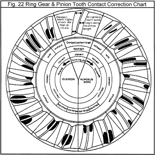
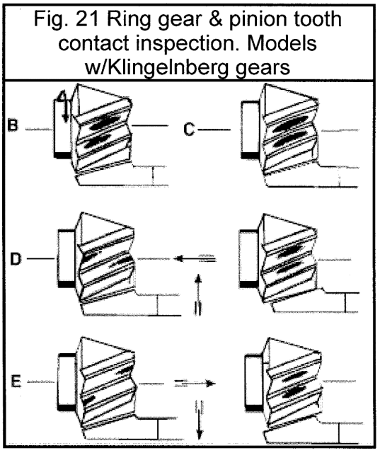
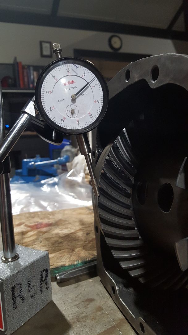
Basically you need to change the thickness of the two carrier flange shims to get carrier in the correct position. Note: this is done while keeping the total thickness of the shims the same (the number we recorded earlier) You should only have to play with these shims. As long as you put the same shim for the inner pinion bearing back in as the one that came out the pinion should be at the correct depth. Again that shim is specific to the casing. Also, the pinion and crown gear are a match set, you should never use a mismatched pinion and crown gear. For the backlash the range you are looking for is 0.0025”-0.0055” per BMW. This is also set by playing with the shims. To check the tooth pattern you need to smear some grease or I used some machinist bluing. You should try and load the diff as much possible as you spin the gears. The backlash is measured with a dial indicator. It can be a very tedious process of changing shims and checking the tooth pattern and backlash before you get it right. Be patient and get it right, this is very critical in ensuring a long life for your diff. It took me a while but this is what my tooth pattern looked like.

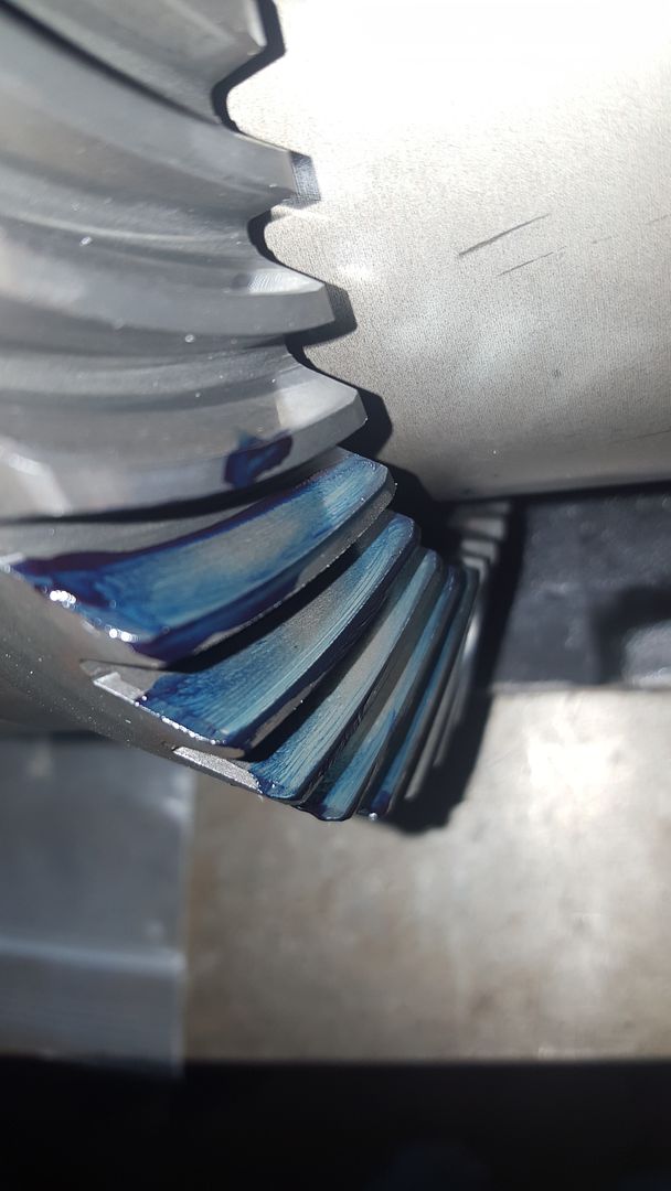
I ended up with 0.004” of backlash, purrrrrfect.
Once you get everything set up correctly you’re pretty much done! Whoow! Bolt on the cover, torqueing the bolts to 40 ft-lb. If you want you can throw a nice coat of paint on it. I actually used a black two part epoxy, we use this stuff on our saltwater pumps at work. It should hold up well to the salty Midwest roads.
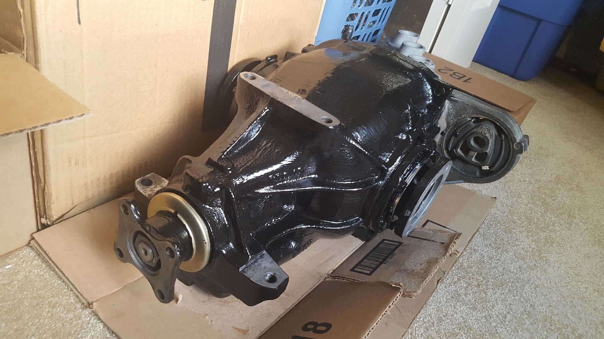
Done! Yay! drink lots of beer

-
No, problem.
Darn, thanks for the heads up. I'll pick up some putty knives.
-
Finished the diff write up, let me know if I F'd anything up haha.
-
Look for thick putty knives with a sharpened edge. I have a stone to sharpen them occasionally and it also knocks off high spots where the sharp edge caught something. You will be surprised how Mich rust is underneath undercoating that looks intact. Mostly around seams. Be careful, mine hasn't been on the road in 2 years, but I'm also married with kids.
Sent from my 831C using Tapatalk
-
Finished up another little side project. A rebuildable viscous coupling. First started with cutting a burnt out one open on a lathe.
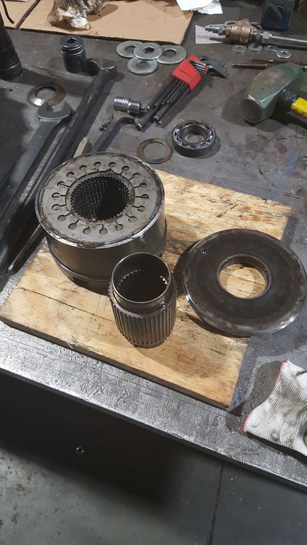
The basic idea was to add an extension to the VC barrel for the addition of an o-ring groove and a snap ring groove. After taking a few measurements I mocked everything up in autocad. I rough machined the ring from CA40 420SS and welded it to the VC.
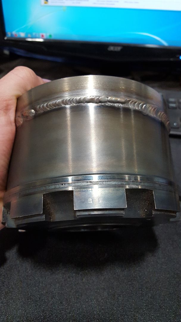
The cover that was removed from the VC was machined to the max ID of the stator plates. Then the VC extension was finish machined for a 0.001"-0.003" loose fit to the cover. Then the o-ring and snap rings were added.
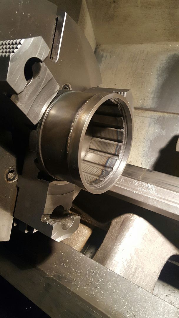
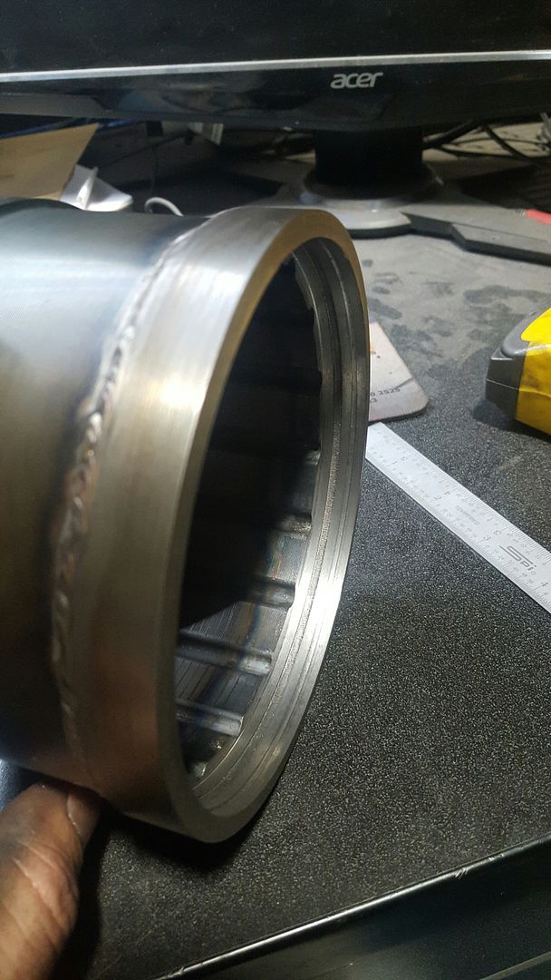
And whala, a rebuildable viscous coupling
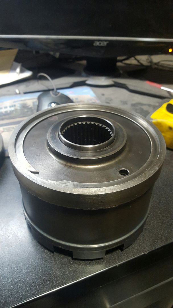
-
Crazy good job Ray=) Did you get your secret santa gift by the way?
Thanks. I did! It sat in front of my door for a few weeks while I was gone for work but luckily my neighbors were decent haha. I'll post a picture tomorrow.
-
How do you remove that massive internal snap ring? I dont see any holes for a tool to catch onto in the picture
There's a big chamfer on the left side (in the picture) that you can pry on with a screw driver to get the end out of the groove. It's actually pretty easy.
-
I also tapped that hole for a 3/8 NPT plug, after removing the pressed ball bearing before I came up with the idea to make it rebuildable. Can also use it to fill the vc with the silicone fluid with the cover on. I made the custom o-ring yesterday so hopefully next week I can pressure test it and put it together for real.
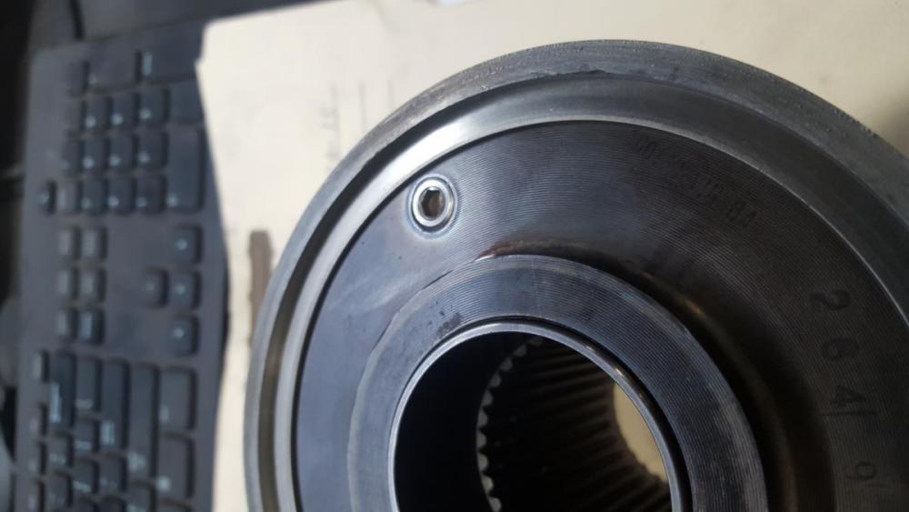
-
Being a magician helps too
-
Yeah, shouldn't see much pressure at all, I just want to make sure my o-ring seals well. I had to use a 0.070" o-ring due to space restraints. Shouldn't be a problem but it'd be shitty if the silicone fluid leaked out right at the get go.
-
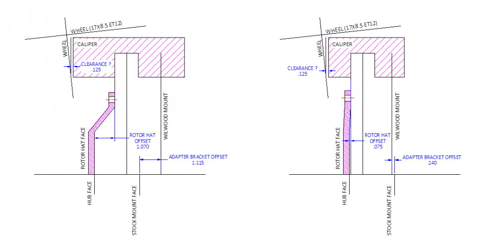
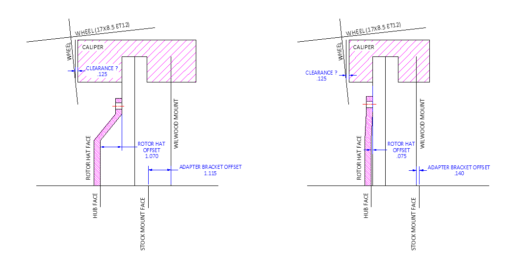
So I'm trying to work out my brakes... and could use some advice

Things I'm trying to decide on:
- How far away the caliper should be from the wheel. Leave more room for different wheel options?
- How far can I move the caliper before the rotor hat and adapter bracket offset is enough to cause an undesirable torque during braking?
- Do I even need to be worried about this torque?The two calipers I have modeled are the Wilwood Forged SL6R (left) and the Wilwood Forged Narrow SL6R (right)
The narrow version is about $75 more a corner, not sure if its worth the price difference, but if the offsets and clearance are an issue the narrow version should be better.
Any help would be greatly appreciated!!








Hello! It looks like you're interested in this conversation, but you don't have an account yet.
Getting fed up of having to scroll through the same posts each visit? When you register for an account, you'll always come back to exactly where you were before, and choose to be notified of new replies (either via email, or push notification). You'll also be able to save bookmarks and upvote posts to show your appreciation to other community members.
With your input, this post could be even better 💗
Register Login