
TehRaydarlover's AWD lover

-
might go a little fast with a starter motor hooked up haha.
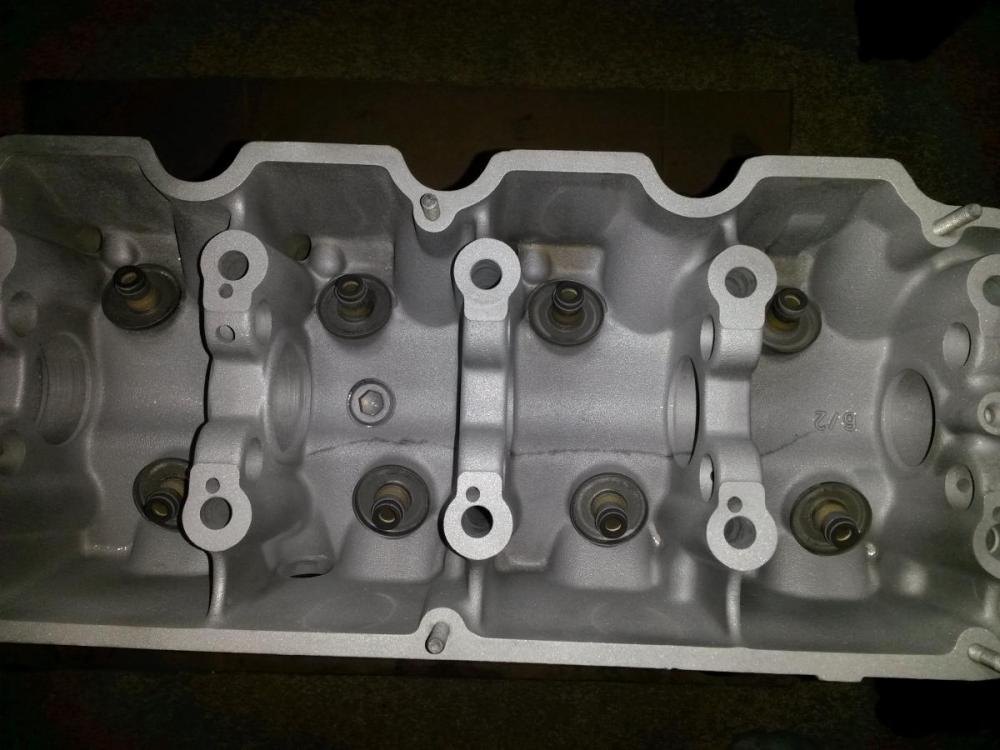
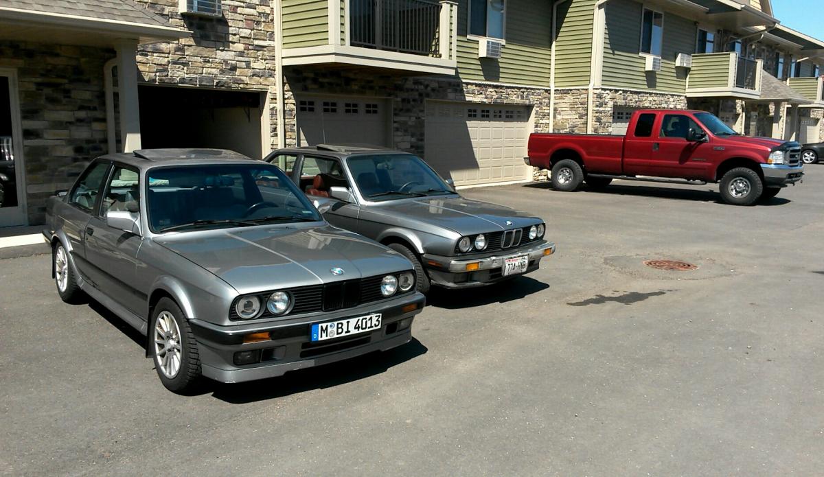
pic of the drug addict:
-
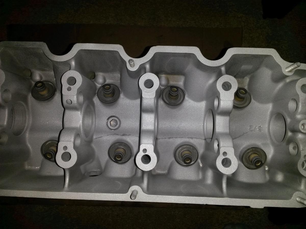
Wow never seen a crack like that. I got a set of LED 9004 hi/lo bulbs coming to try out on the Maxima. If they work pretty good I am interested in putting them in my new Hella lights for my e36. Did you/ could you try the LED in the projector low beams to see how the pattern looks?
-
Yeah it's a pretty impressive crack. The cam and rocker arms that were in it are quite f'd too. I didn't get the lows yet because I have smileys. He said with the bulb placement(too far forward?) it creates a hot spot. LEDs work fine for regular ellipsoids. I might try to do a bi-xenon or just regular hit for the lows. We'll see. Guess I could/should have just tried it with a fog light bulb.
-
I've been in Arkansas for work and today I get to see my car for the first time in a month, excited
 Hopefully there's a pile of car parts waiting at my door.
 -
Trying to decide if I should use the head I currently have for my turbo build. It has been ported and had new valve guides and seals installed but it has also been skimmed down to the dimples (can't see them anymore). I would like to use an OEM type gasket and o-ring the block, but with the stroke/rod/piston combination my compression ratio is going to already be on the high end of where I would like it to be. Trying to find a solution to bring my compression ratio down with out causing the head gasket to be the weak link in the engine. The stock head height is 4.925", I still need to measure mine to compare but I'm thinking its going to be significantly less. Using an OEM 2.05mm repair gasket I could get 0.012" back, but I'm not sure its going to be enough. Does anyone know if there is an OEM style gasket available that is thicker than the 2.05mm. My goal for the engine is around 500hp. I've looked at the MLS head gaskets available and you can get a very wide range of gasket thicknesses. Does anyone have any experience with a MLS head gasket in a high power m20? I still need to do more research but this is what I've come up with so far. Any advice would be appreciated!
-
Do they make a cutring gasket for m20's?
I am running a Cosmetic MLS on my M3 and have had no issues with it during the 2k miles it's been in there.
A cut ring gasket is what I originally wanted to go with, the only place I found was Pure Performance Factory, Hard to find any information about the gaskets. They don't list any gasket thicknesses so after I realized the head had been decked so much I kind of stopped looking. If you know of anyone else who makes them I'd like to know! http://server.pure-pf.com/webshop2/index.php?id_category=162&controller=category&id_lang=1
My concern with the thicker MLS gasket is that I would have a thicker cross section open to the cylinder, would think it would see a lot more stress than normal. idk maybe I'm worried about nothing.
What kind of CR do you think you would end up with if you go with a thicker oe gasket? Have you thought about embracing the higher compression and running a methanol injection setup? Otherwise i think the MLS will work fine.
Kind of an intro to a whole new topic but I my at the point where I have everything except pistons, I would like to use Metric Mechanic 3.1L turbo pistons. I've called and talked with Jim and with their pistons they also run a 21mm wrist pin and 134.5mm rods combo yields a 8.3:1 CR. I already have a set of 135mm carrillo rods that I would like to use, I can't remember exactly but I believe with the 135mm rod and 22mm wrist pin the CR would be in the mid 9's. Which is a little higher than I would like to have. I have thought about methanol injection, and would be fine, even If I can get the CR lowered it wouldn't be a bad idea to have it. Get one of those OEM extended gas tanks that fits in the trunk and have that be the meth tank, would be pretty slick. A higher CR would be nicer for off boost driving. Maybe you have some advice on piston manufactures.
Been kind of dragging my feet trying to decide what to do about this.
-
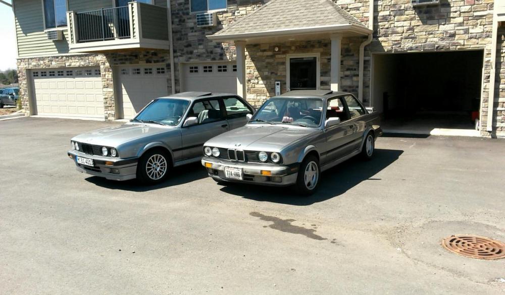
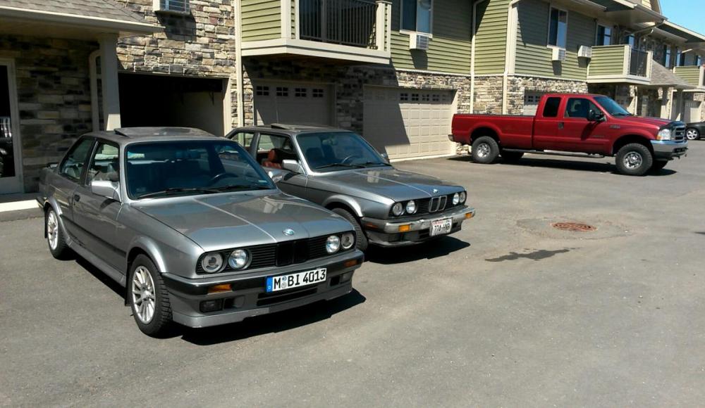
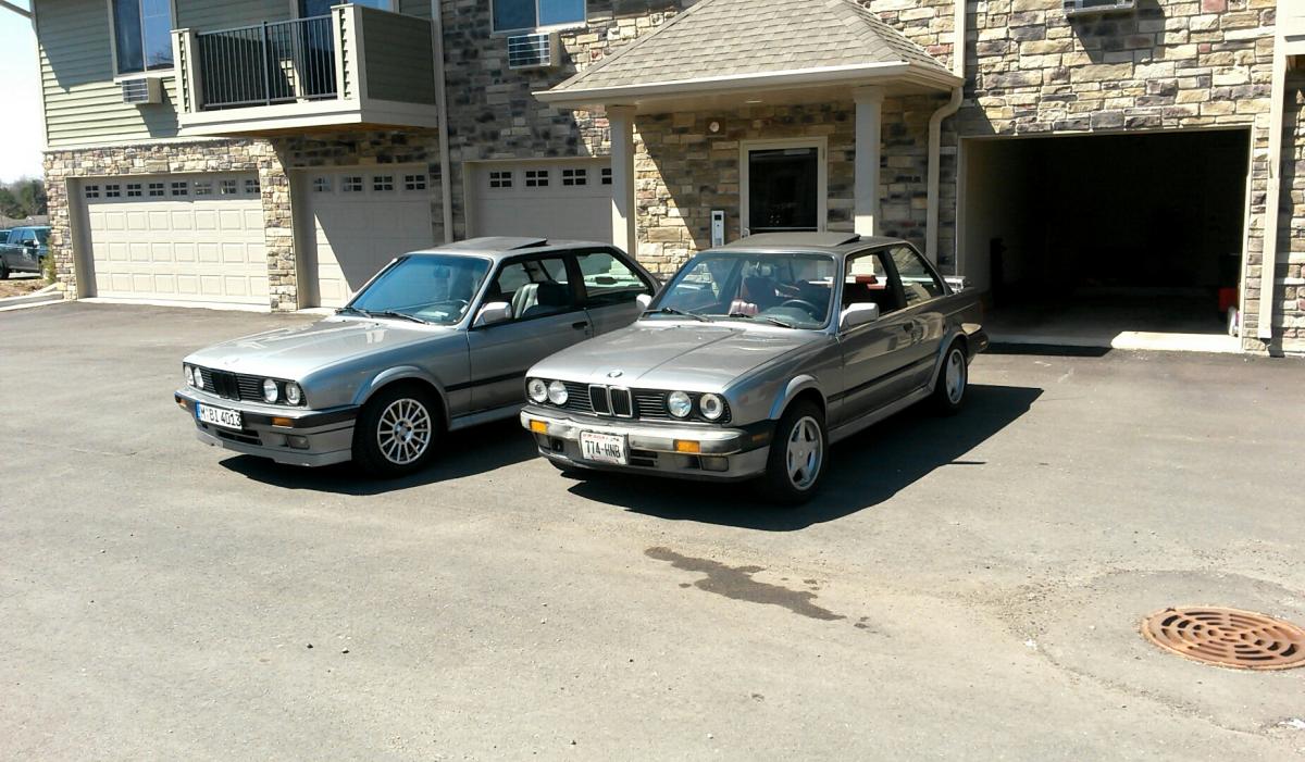
Oh yeah, I haven't been updating this thread like I should but I bought another 88' ix haha. It's quite the beater but its fun.
-
Thanks!
Measured the head height this morning. It's 4.898" so compared to stock it has had 0.027" shaved off.
-
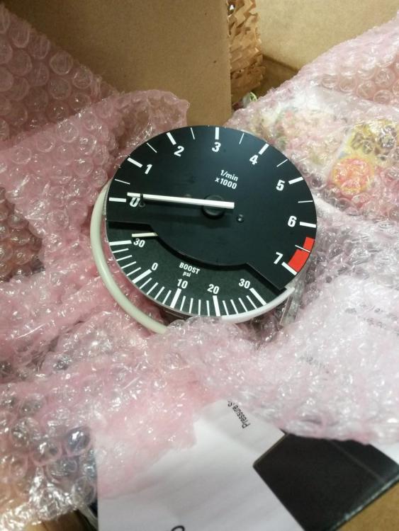
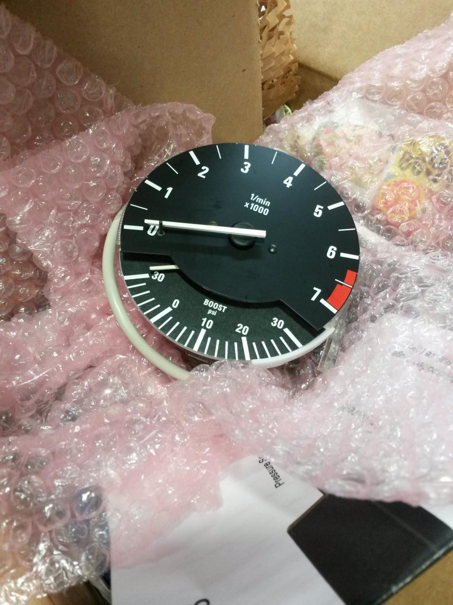
Still haven't decided what to do about the head, but this came in the mail on Saturday. I freaking love it.
-
Awesome. This is the new mod E28 guys are doing. Not sure if this could be worked into a e30 cluster too.
-
Nice! I have something similar for an AFR gauge that goes in one of the button slots in the dash. That would be pretty cool get something similar for the e30 cluster.
-
The car is currently on jack stands getting completely disassembled
 This is pretty much as it sits right now.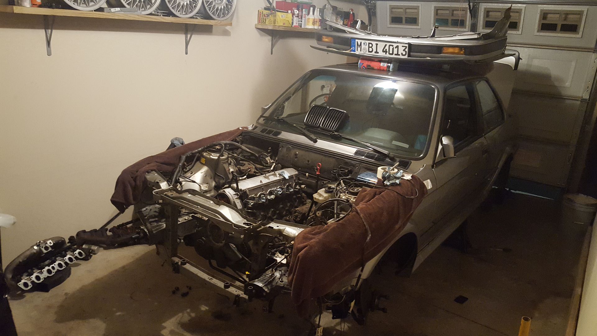
As of right now the rear suspension, fuel system, brakes, cooling system, AC system, Intake, exhaust, interior, and wiring harness has been removed or as removed as I can get it. The disused parts pile has been growing!
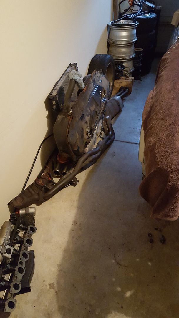
I ran into a bit of a problem getting the rear suspension down. The two allen head bolts holding the subframe bushing bracket would not budge. I ended up taking the electric cut off grinder to them, and accidentally set the rag I had between the body and the jack stand on fire lol. Luckily my apartment doesn't have fire alarms in the garages haha. The next problem was that the fit from the subframe bushing to the undercarriage of the car, where that long bolt goes through, would not budge. I ended up taping the subframe bushing with a 9/16" tap and threading a bolt in to beat it out from inside the car. Kind of a pain but it eventually came down.
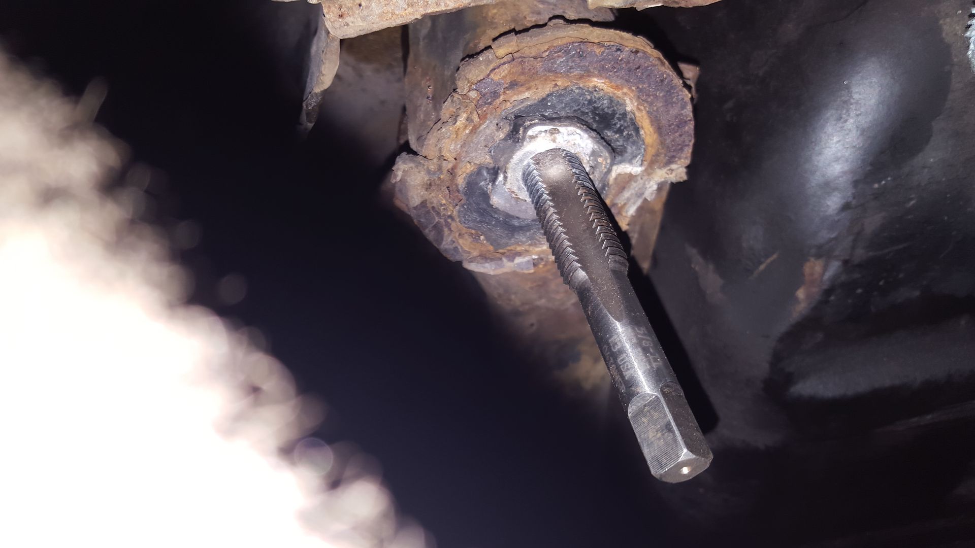
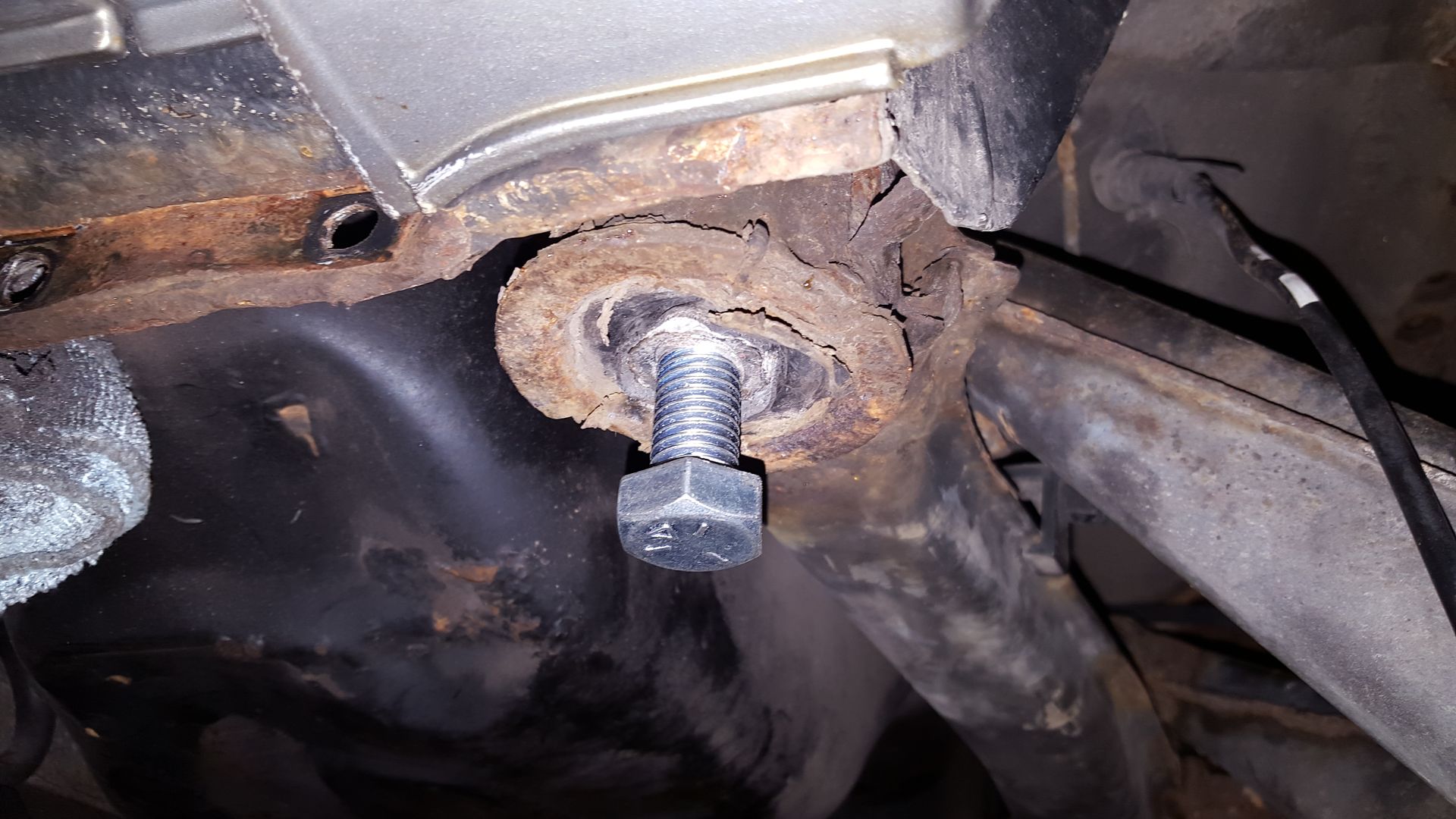
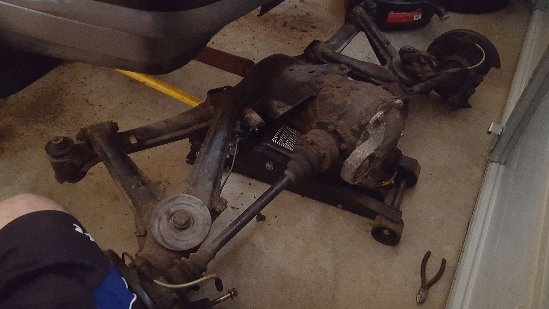
The next thing for the car is to wire wheel the undercoating off as best possible and preparing for some rust repair. Then the rest of the drivetrain will come down.
Along with working on the car itself I've been working on a lot of side projects, diffs, t-case, engine, etc. I'll post the write up for the rear diff sometime this week. I'll probably post the side projects as they are finished so everything doesn't get scattered. Cheers
-
I picked up a couple rear diffs a while ago so I decided to tear them apart and rebuild the better of the two. It went pretty smoothly, biggest pain was getting the old bearings off the carrier. I took a lot of pictures so I was thinking of doing a How to/DIY. Keep in mind this is for a 3.91 Viscous LSD, so no clutch disk silliness haha.
Here are all of the parts I used. I got the majority of the parts from Blunt and ECS Tuning, I think the total was just over $200 for everything. This list should be the same for a clutch type diff… I think.
Rear Gasket P/N 33111210405
Carrier bearing x2 P/N 33131213893
Pinion Bearing P/N 33121203616
Pinion Bearing P/N 33101214099
Shaft seal P/N 33101214099
Shaft seal x2 P/N 33107505602
Securing plate P/N 23211490120
o-ring x2 P/N 33111214144
dust cover P/N 33121200284
Dust cover x2 P/N 33131208006
Drain plug x2 P/N 33117525064
Speed Sensor P/N 62168357020
Bracket P/N 33111206076
Securing plate P/N 62161365817
o-ring P/N 33111206166Onto the rebuild!
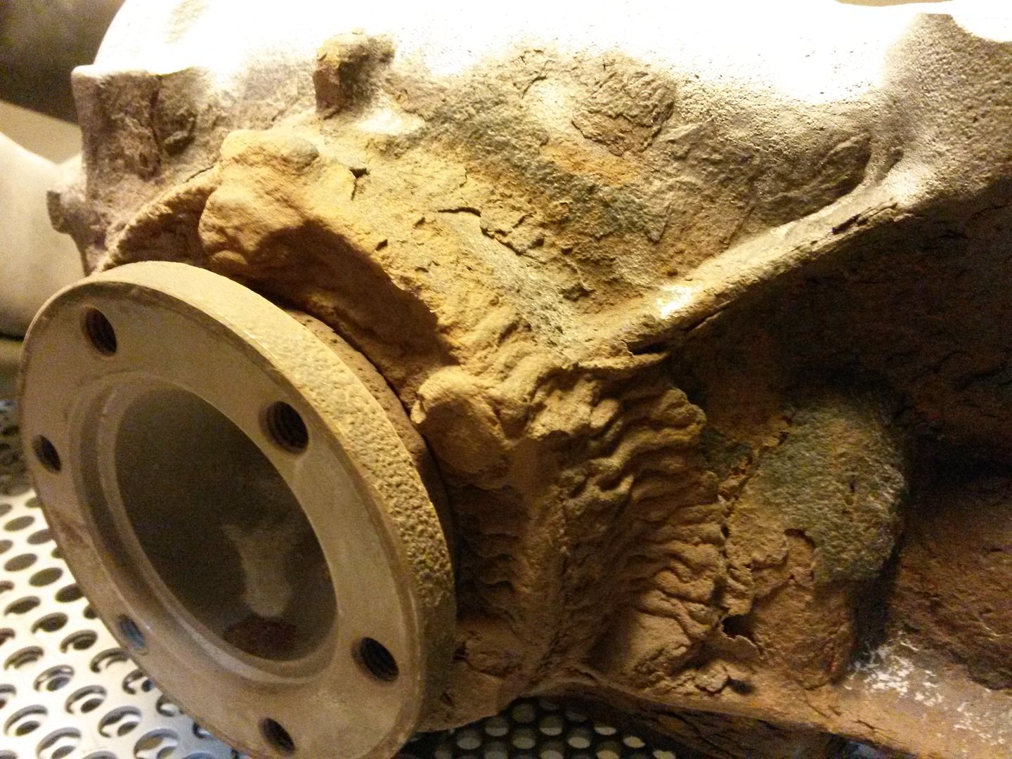
First thing I did was sand blast them. This was one of them… I didn’t know they had E30s on the Titanic haha. This casing was really pitted; I decided to use the other case which had very little rust.
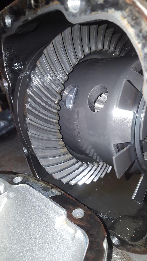
With the diff clean I drained the oil and popped the cover, everything looked surprisingly healthy. No excessive wear on the gears or glitter in the oil.
Prying out the output flanges with a heal bar, the axle is just held in there with a retaining spring clip.
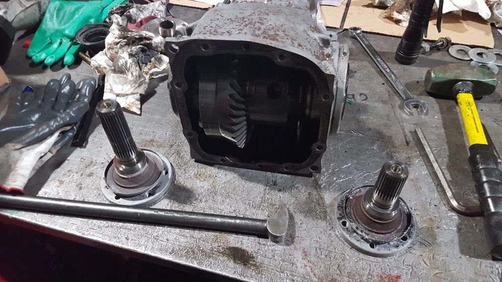
Be sure to support the carrier while unbolting the covers, the carrier will just fall right out with these removed.
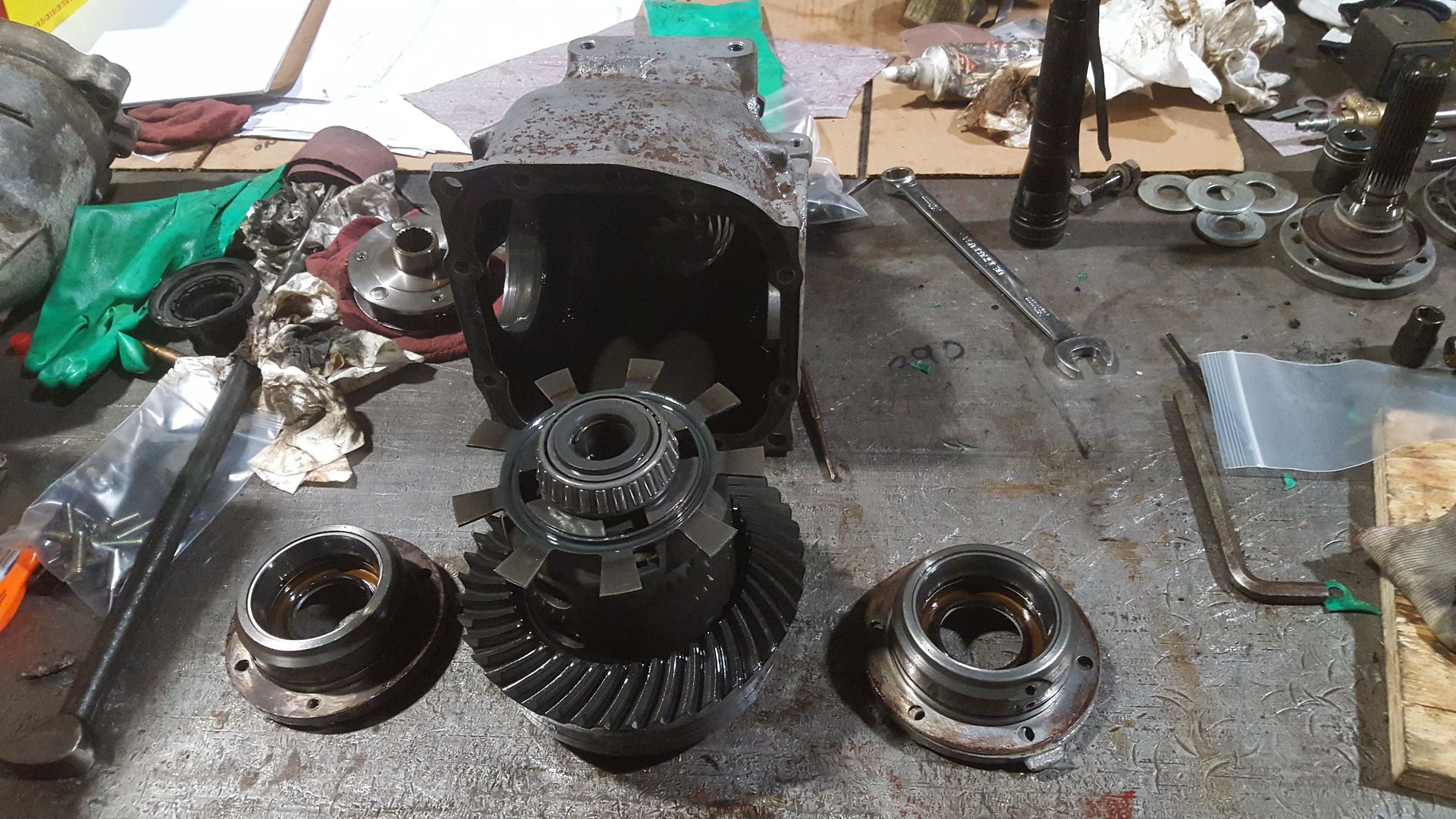
Remove the crown gear bolts, I had to break out the 1” impact for this.
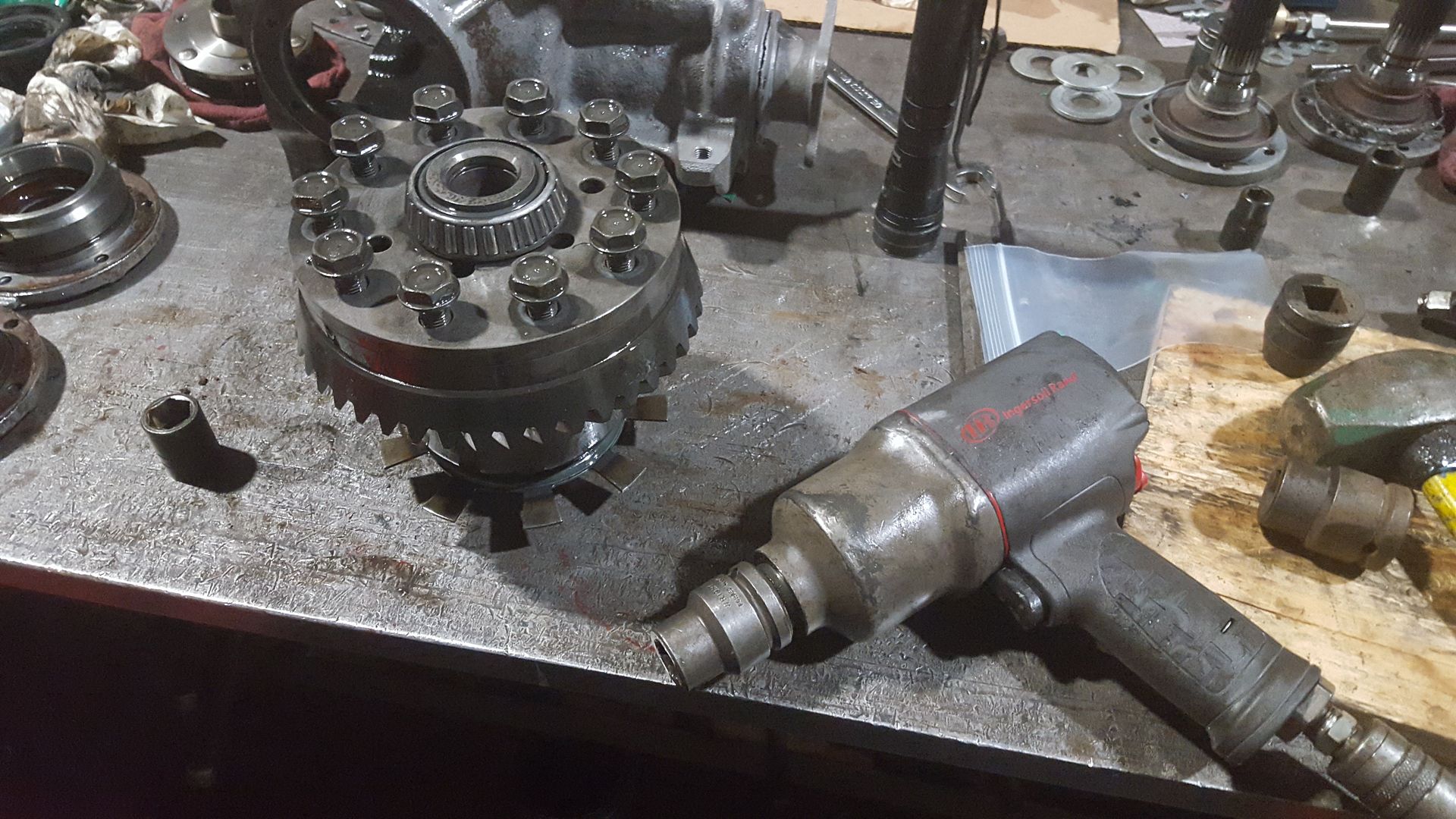
The crown gear bore is a slight interference fit to the carrier. I had to use a punch to tap it off. A brass punch would be ideal but I didn’t have anything small enough. Be sure to put a board or something under the gear so you don’t chip a tooth when it eventually falls off. Also to get the signal wheel for the speed sensor off all you need to do is throw some heat on it and it will fall right off. I would avoid hitting it with a hammer as you kind of want to keep it straight.
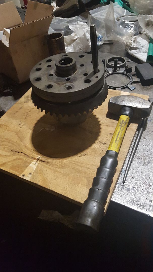
Then there are two 6mm SHCS holding on the cover. Remove them and thread them in backwards a little bit. Then tap the cover off with a punch.
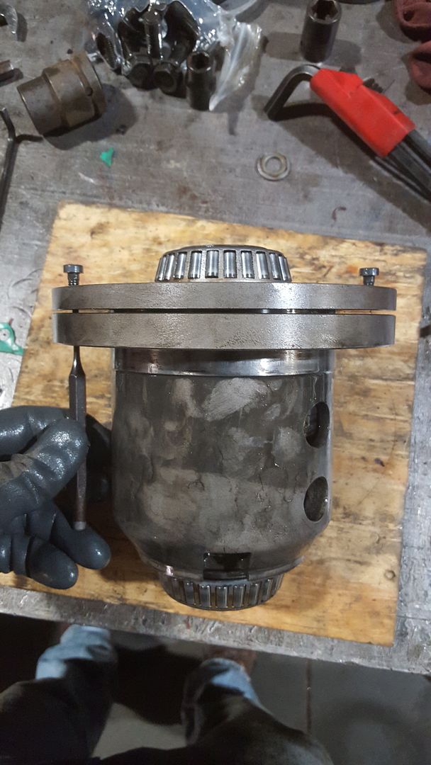
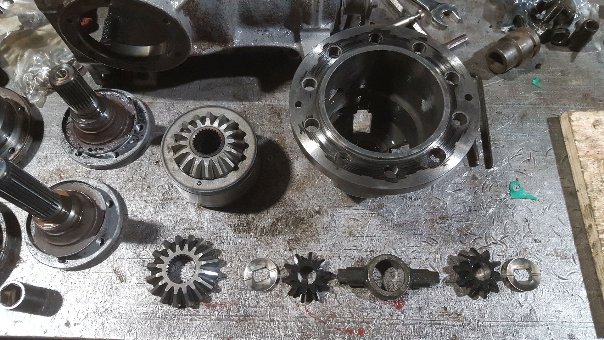
With the cover off everything can come out of the carrier. This is what you’ll be looking at.
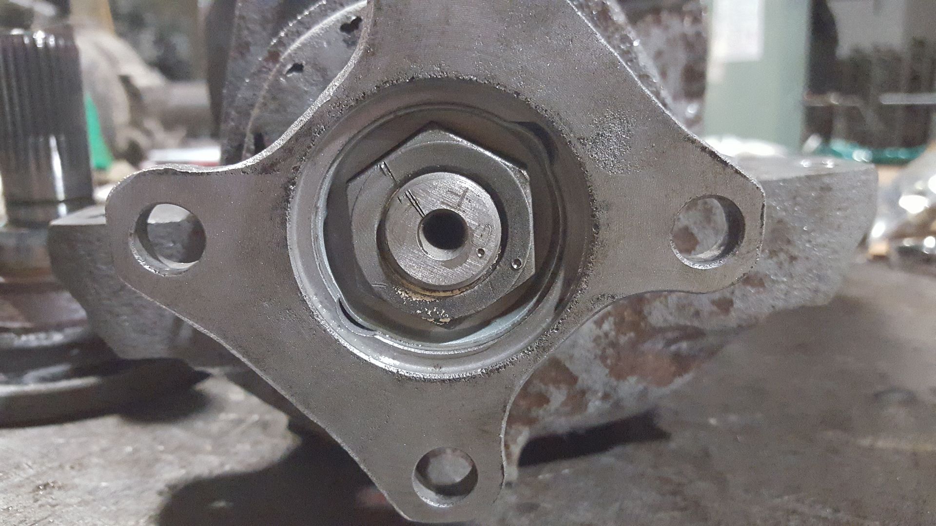
To get the pinion out of the casing you have to first pry out the locking plate surrounding the nut. Stamping the nut and pinion with match marks will give you a good idea of when your getting close to the correct bearing preload. I'll go over this more later. With the retaining plate out remove the nut with an impact.
The input flange should just pull off but it may be held on there by some corrosion. You may need to pull it off with a 2/3 jaw puller. With the input flange off the you just have to give the pinion a few firm taps with a lead hammer and it will fall right out. Again be sure to put a piece of wood or something soft for it to land on when it falls out.
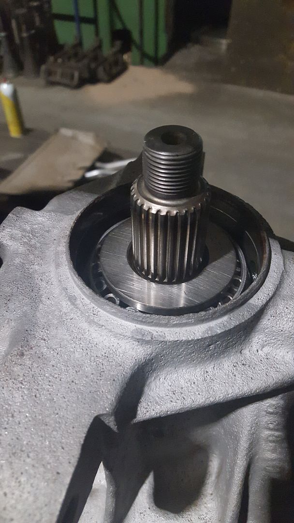
With the pinion out your left with this.
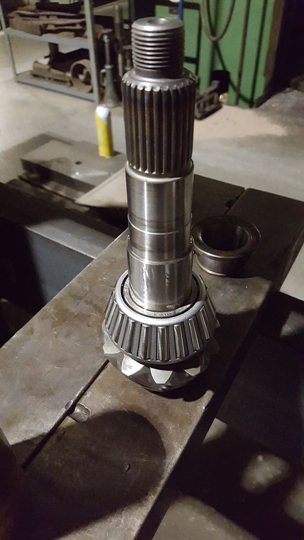
Great everything is apart, have a beer.
-
This is where it gets rather exciting
between the two diffs I was disassembling they had two different designs for the viscous coupling. The first was a completely welded unit just like the transfer case. The second had a big retaining clip holding the one end in!! Which means it can be rebuild without cutting it open on the lathe!! Cool Confirmed that the overall lengths of the two VC we roughly the same so either one could be used in either carrier. Unfortunately I have no idea what year model ix these came out of 
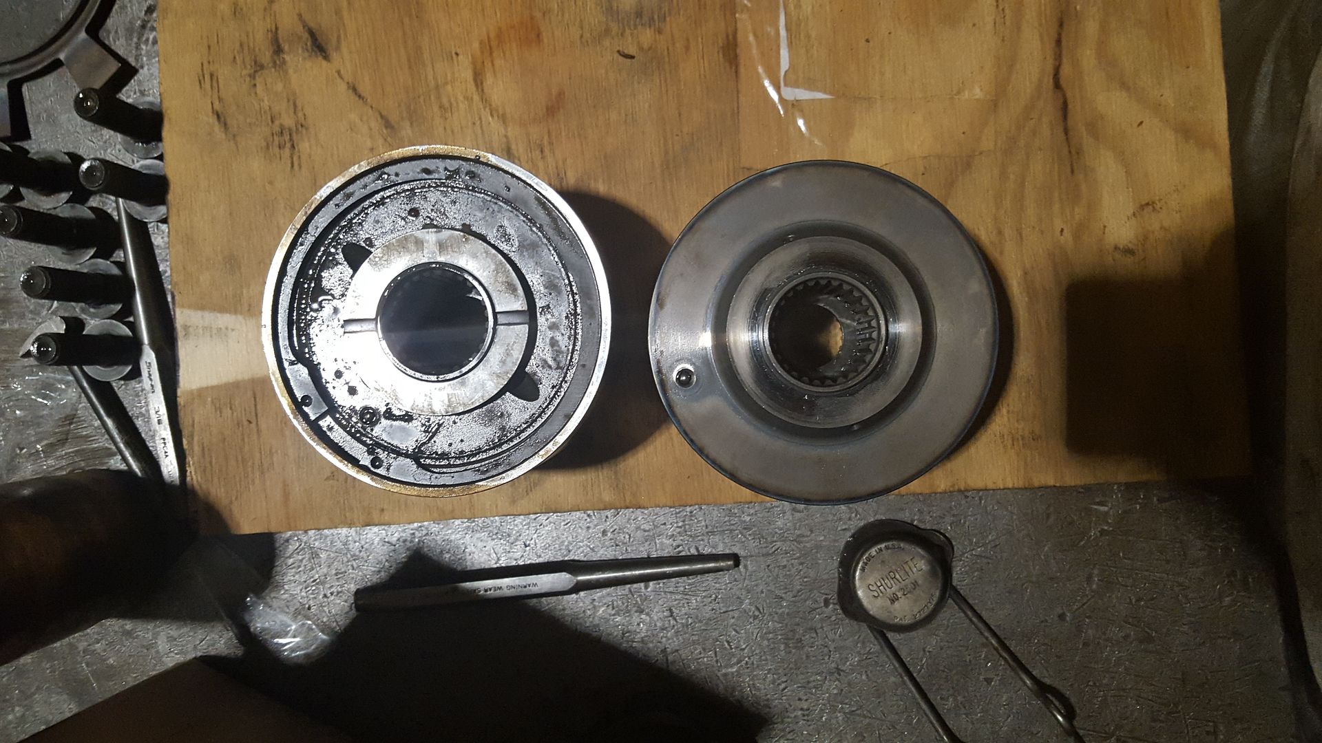
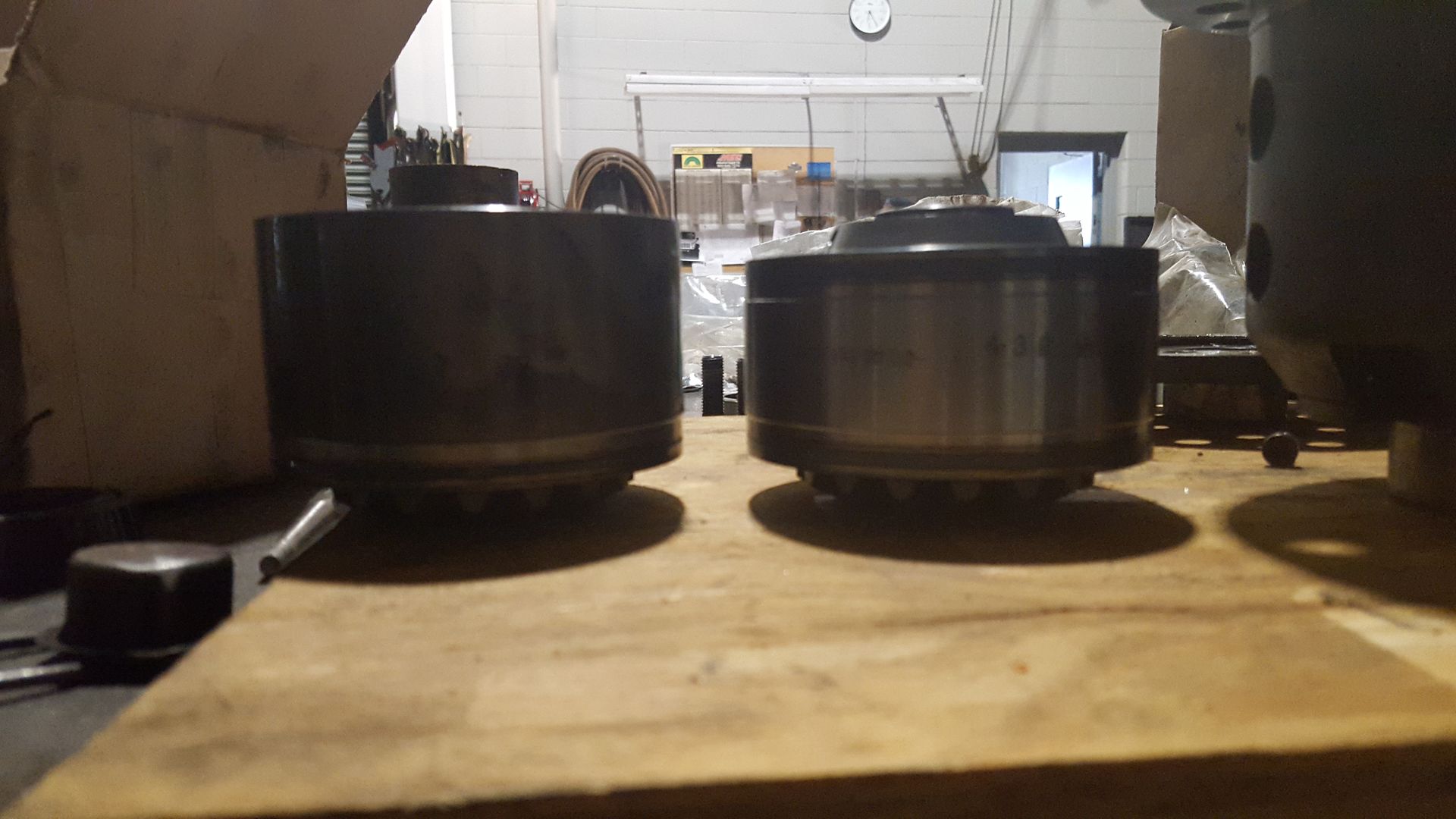
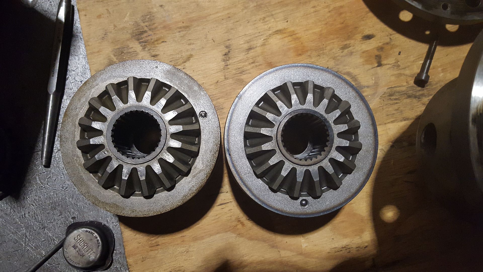
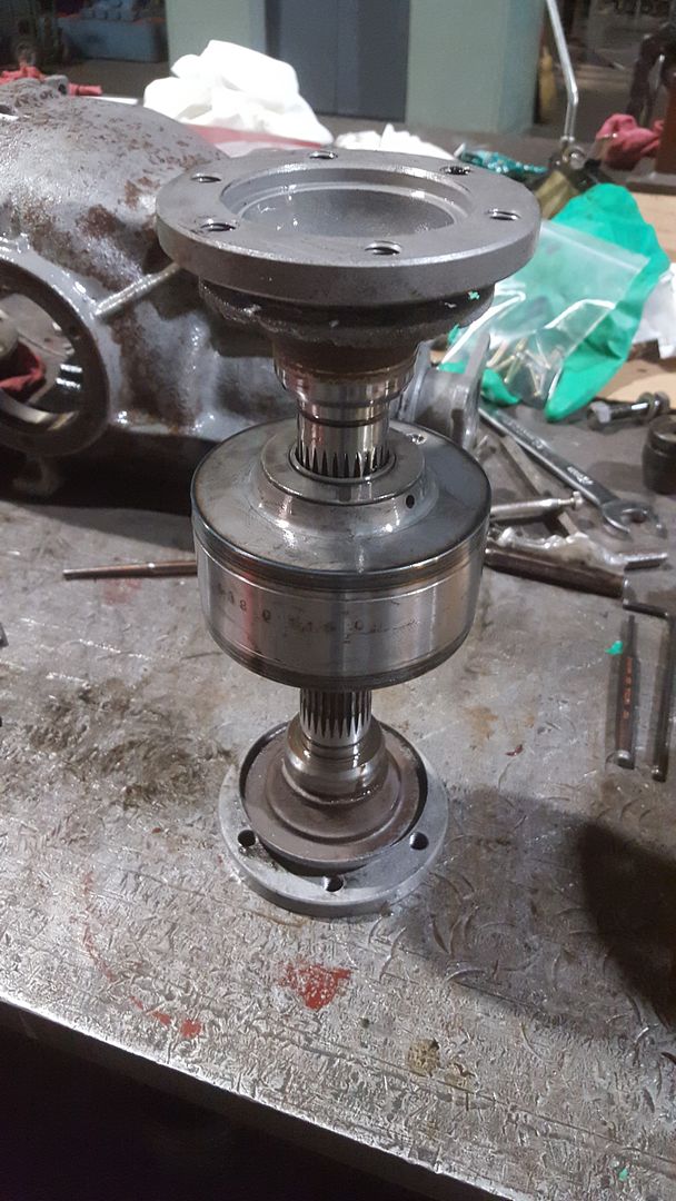
By inserting the output flanges in either ends of the VC you can spin it by hand and test the VC. Comparing the two the welded VC produced noticeably less resistance. The VC with the retaining clip was very strong, I could bearly get it to move fast enough to be able to tell it was moving haha. So with this result I decided to use the VC with the retaining clip in my rebuild. Against my curiosity I decided not to open it up... if it isn't broke don't fix it. At some point I might cut the other VC open and have a look see. I'm sure it has the same type of disks in shear as the VC in the T-case. This also gave me an idea that you might see later in my t-case rebuild

-
So now with everything in the carrier taken apart I just looked for any abnormal wear on the gears and shims. I did notice a small gall on one of the spider gears. I took some 600 grit sand paper and polished the high spots out. With everything else looking good we can reassemble the carrier just as it came apart. Before bolting on the end cover, you should stone the mating faces to remove any high spots or dings from rolling around on your work bench. You will see me stoning faces a lot coming up, it’s really critical that this is done to avoid any sort of misalignment that will show up in your gear mesh pattern ultimately reducing the life of the diff.
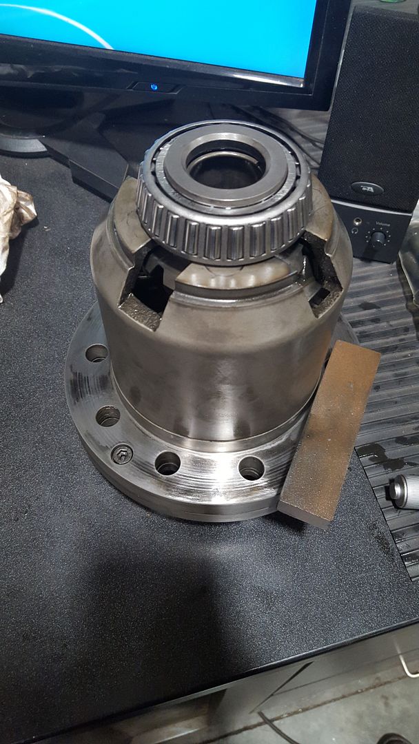
Next we can reinstall the crown gear. Again you should stone both of the mating faces. You are going to have to chase the threads in the crown gear. BMW used a thread locker and you need to clean it out before reinstalling.
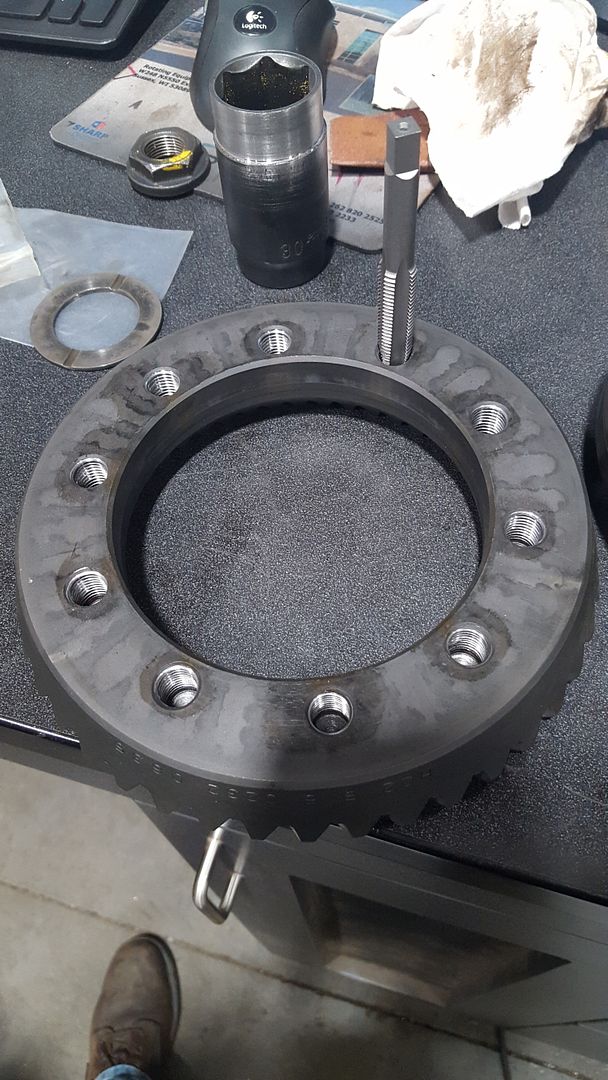
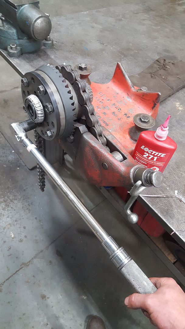
With everything clean we can bolt the crown gear on. Because the crown gear is a slight interference fit to the carrier just install 4 old bolts and use an impact alternating bolts until the gear is fully seated on the carrier. Then you can juice up all of the new bolts with Loctite and hand tighten them, BMW does spec out to replace these. The crown gear bolts are torqued to 140 ft-lbs. I did one pass at 100 ft-lbs then a final pass at 140 ft-lbs.
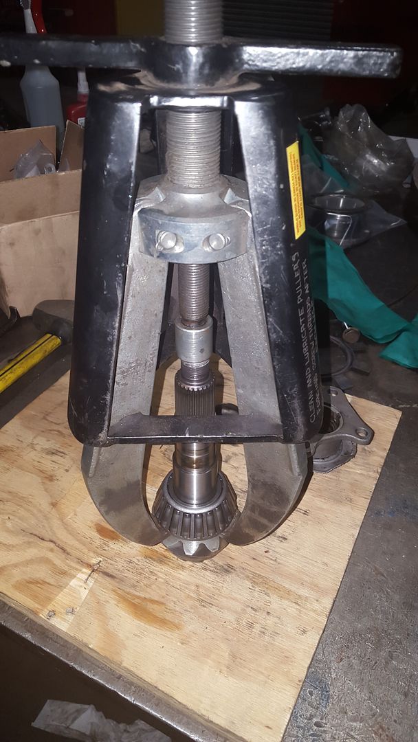
Now it’s time to remove the old bearings and press on the new ones. You might be able to get the bearings cages and inner races off with a large 3 jaw puller, but I ended up using a clam puller and a hydraulic jack.
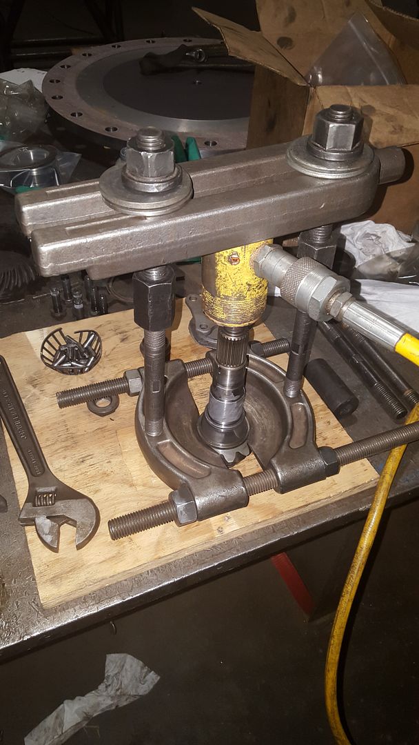
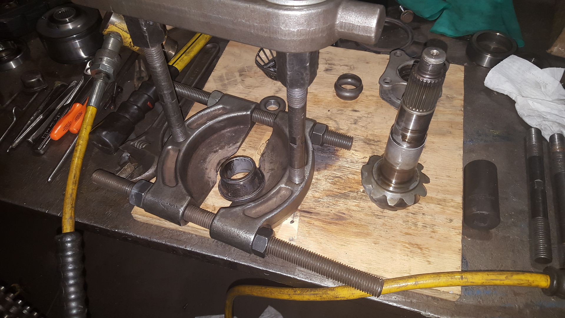
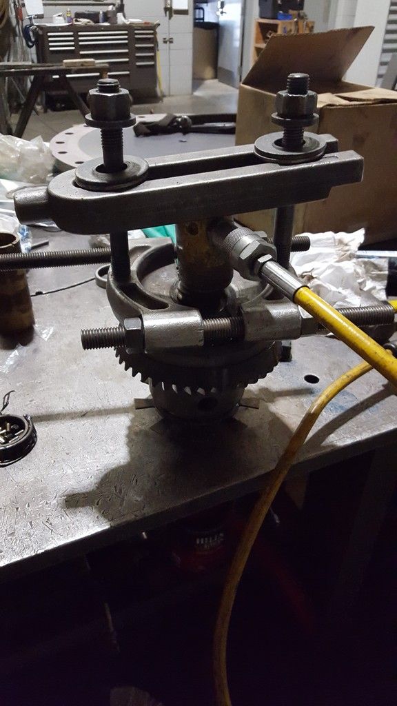
To get the outer races out of the carrier flanges and casing you’ll need to a hunk of metal with a slightly smaller diameter and either beat them out with a hammer or with a press. Be careful when you press out the races out of the casing as there is a shim under the inner bearing that you NEED, DON’T LOOSE IT haha. It would be a huge pain to try and recalculate the required thickness. The shaft seals can also come out of the carrier flanges.
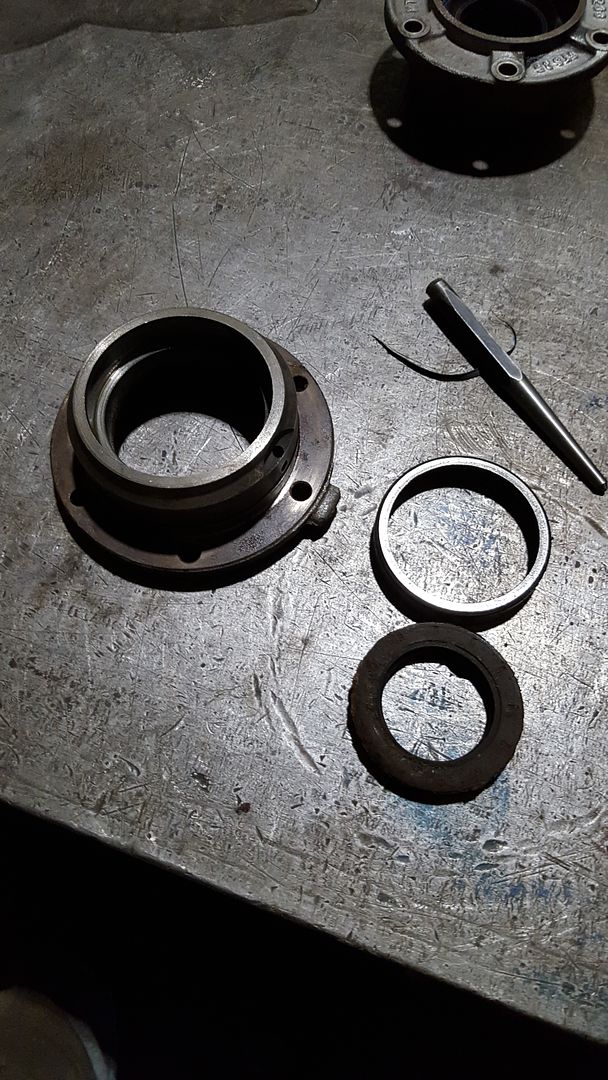
Once you have the outer races removed take them over to the belt sander and take enough material off of the OD that you can freely slip it in and out of its receiving bore. We’ll use these to reinstall the new outer races. With the outer races removed you can do any final cleaning of the casing and carrier flanges. My carrier flanges had some left over corrosion outside of the shaft seal that I cleaned up so I didn’t damage the new seals during installation. I gave the receiving bores a LIGHT coat of RTV and tapped the new shaft seals in with another piece of metal with a slightly smaller OD.
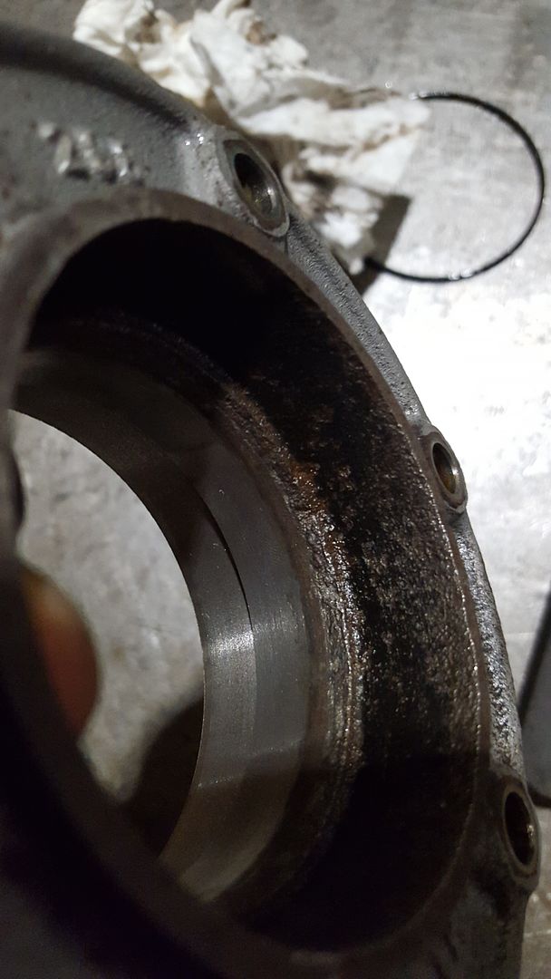
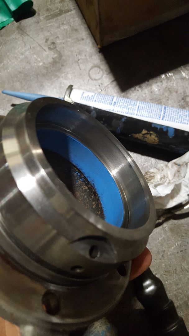
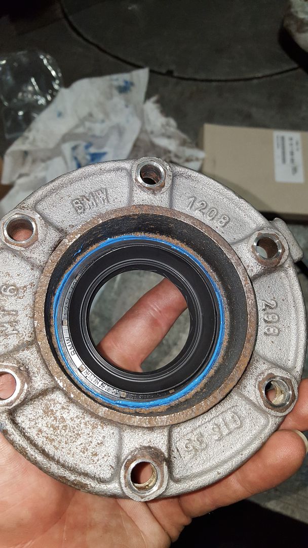
After giving the receiving bore a coat of oil it’s time to press in the new outer races. Try and get the new race started as straight as you can in the receiving bore. Then set your old race with the sanded OD on top of it and press it home.
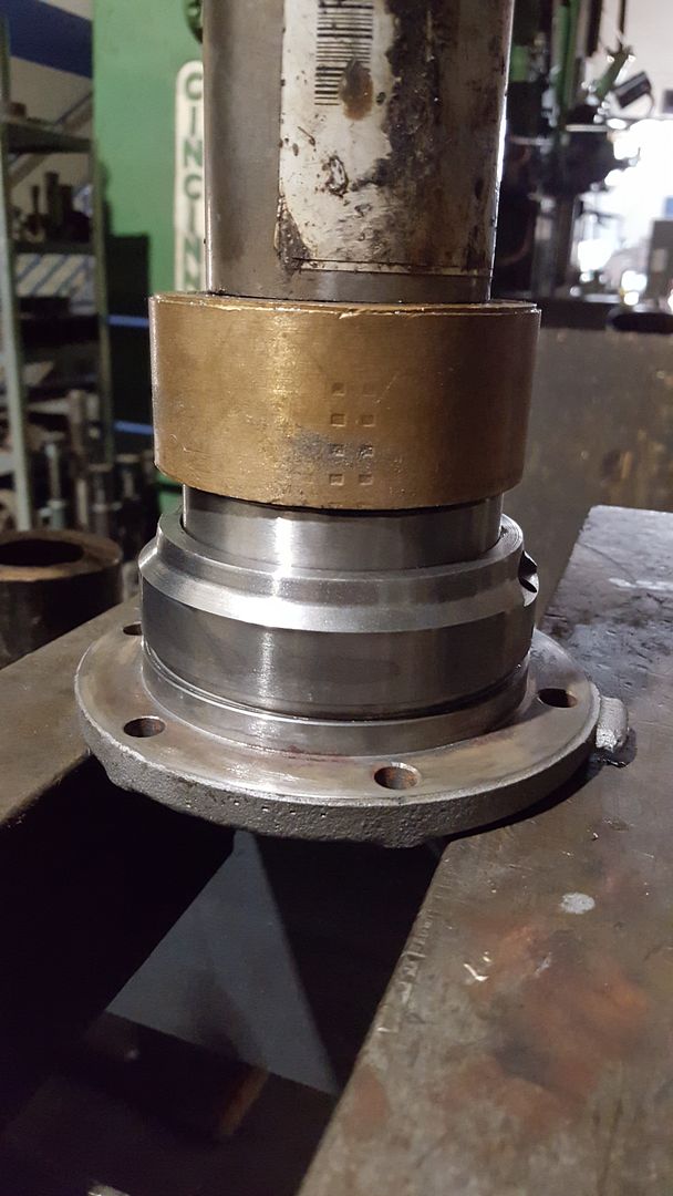
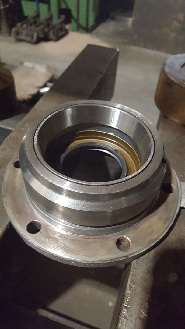
Do this also for the outer races that go into the casing. Remember to put the shim back behind the inner bearing’s outer race.





Hello! It looks like you're interested in this conversation, but you don't have an account yet.
Getting fed up of having to scroll through the same posts each visit? When you register for an account, you'll always come back to exactly where you were before, and choose to be notified of new replies (either via email, or push notification). You'll also be able to save bookmarks and upvote posts to show your appreciation to other community members.
With your input, this post could be even better 💗
Register Login