
E21 project thread
-
I am definitely working my ass off to make it on Sunday. Gonna be putting in some long and late hours the next 2 days.
-
It has definitely been awhile since I have updated this. Obviously I didnt make it to the 5er meet with the car. I busted my ass getting everything done and together, she just didnt want to fire up. Since then, I have been chasing this no spark issue forever it seems. I tried everything and tested everything to no avail. I was to the point of just giving up till next spring, but decided to try out the EDIS-4 and see if that got spark. First try after connecting things together and no spark as well. GAHHH!!! I then decided to completely take apart all the wiring for the EDIS since some of it the PO did and I wasnt certain it was done right. After rewiring I bench tested it and sure enough, the plugs all sparked perfectly. Threw the positive & ground in the car and once again, sparked perfectly. So, I threw the plugs back in the head, turned the key, and she fired right up, FINALLY! OH MY BAGOSH!!! I am so freakin happy!!
Now is the time to finish up the little things around the car and wire everything in permanently. I decided to go with a separate fuse panel and for the EDIS, Megajolt (MJ), and throw the gauges on it too for good measure. Most of it will be mounted in the glovebox except the EDIS module and coilpack, obviously. I used a spare sheet of plexi that I had laying around and mounted the circuit breaker, relay, fuse panel and MJ with 3M tape.
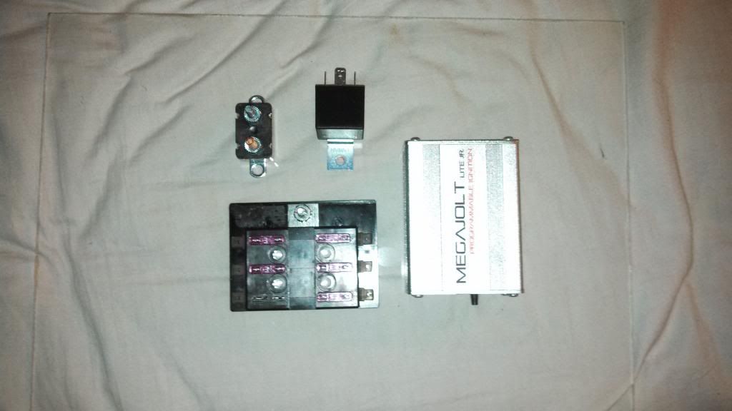
I then went ahead and wired everything up. I decided to take the constant power and ground from the glovebox flashlight circuit since I dont have the flashlight anyways. Turns out that some female bullet connectors fit perfectly on the pins of the flashlight circuit. All-in-all I think it looks great and of course, works like a charm.
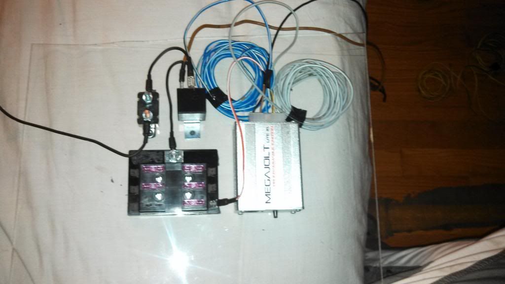
Now all I have to do is finish the wiring in the car and this part should be good to go. Then its just odds and ends stuff and hopefully I will be driving it this weekend. Fingers crossed!!
-

-
Dont remind me!

-
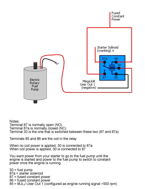
Finished up the permanent wiring and she fired right up again. WOOHOO!!! One problem is I am currently running the car with the fuel relay jumpered since that was tied in with the stock ignition wiring. I will be using output #1 from Megajolt as the signal wire to the fuel pump relay. This will allow the fuel pump to run whenever the rpm's are above a preset value by me (I will be using the lowest setting of 500 rpm). For the safety factor if for any reason the car gets disabled but the power is still on, the fuel pump will shut off once it drops below 500 rpm. Below is the diagram I will be following. Just have to compare it to the stock wiring diagrams to see how the current fuel relay works and is wired.
I also got the front sway bar installed, as well as the front alpina brace installed. I had a leaking hose from the brake reservoir to the clutch master cylinder, so I ended up removing the old one and retrofitting a new setup on. No more leaking. This brought me to bleeding the brakes again which went well, but when bleeding the clutch slave cylinder, I quickly realized its damn near impossible to bleed it by yourself. Will have to wait till I can get some assistance with that.
So close!
-
The world of programmable engine management is a beautiful one that all car nuts should experience
 You are an hour or so away from being able to do burnouts.
also... im serious about coming over to help at 6:30am.
and im serious about the burnouts
-
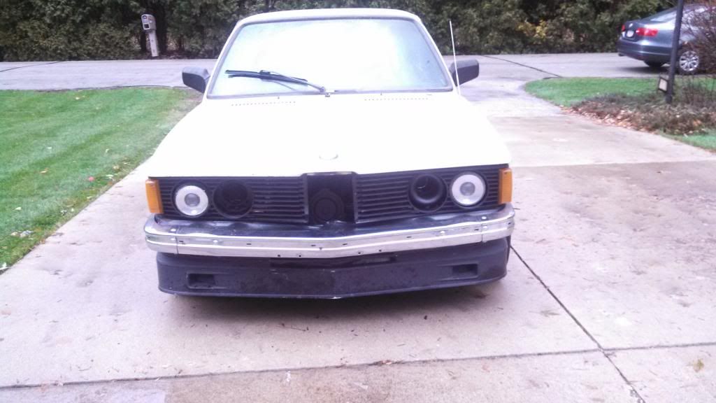
She is alive and kicking!!! Took her for a short drive around the neighborhood and the new suspension, steering, shifting all feel amazing!! Like a freaking go-kart on rails. She goes pretty nice as well with the new megajolt ignition system. It has a coolant leak which I will have to address, but at least its external and not internal. Still much more to do to her till completely done (yeah right, done), but all-in-all I am super happy!
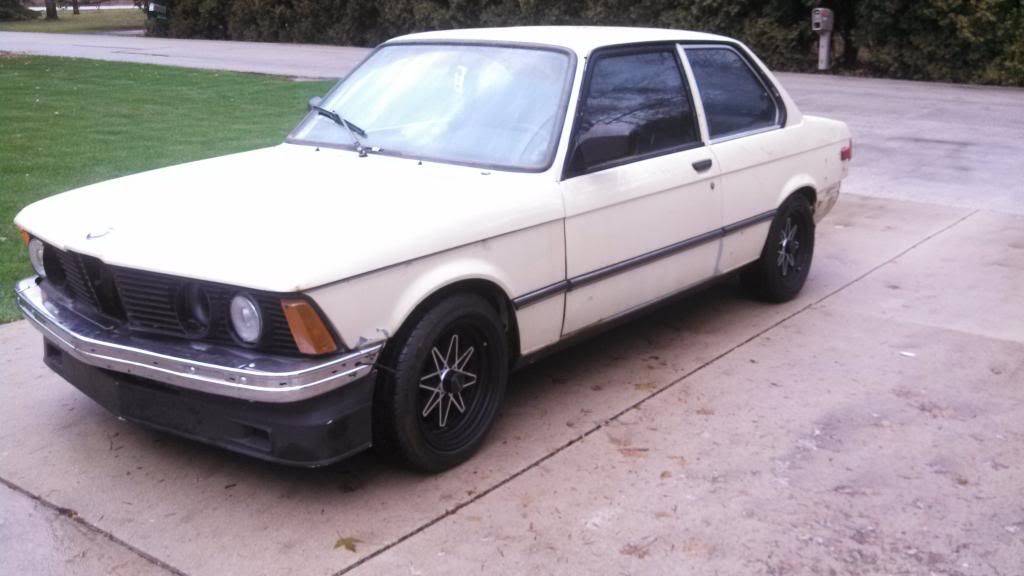
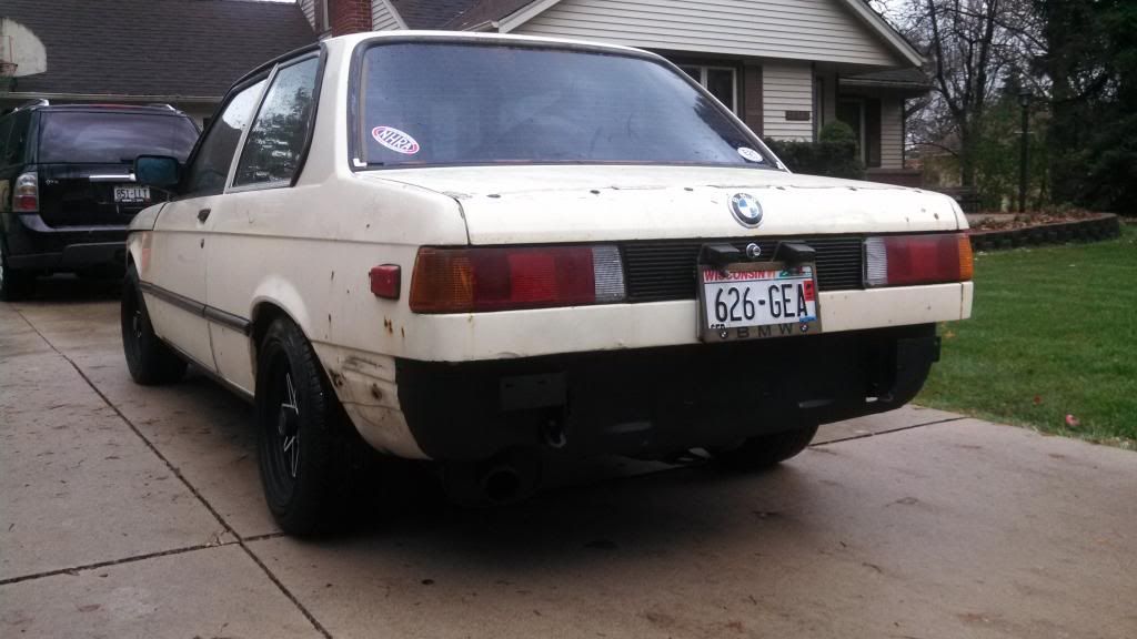
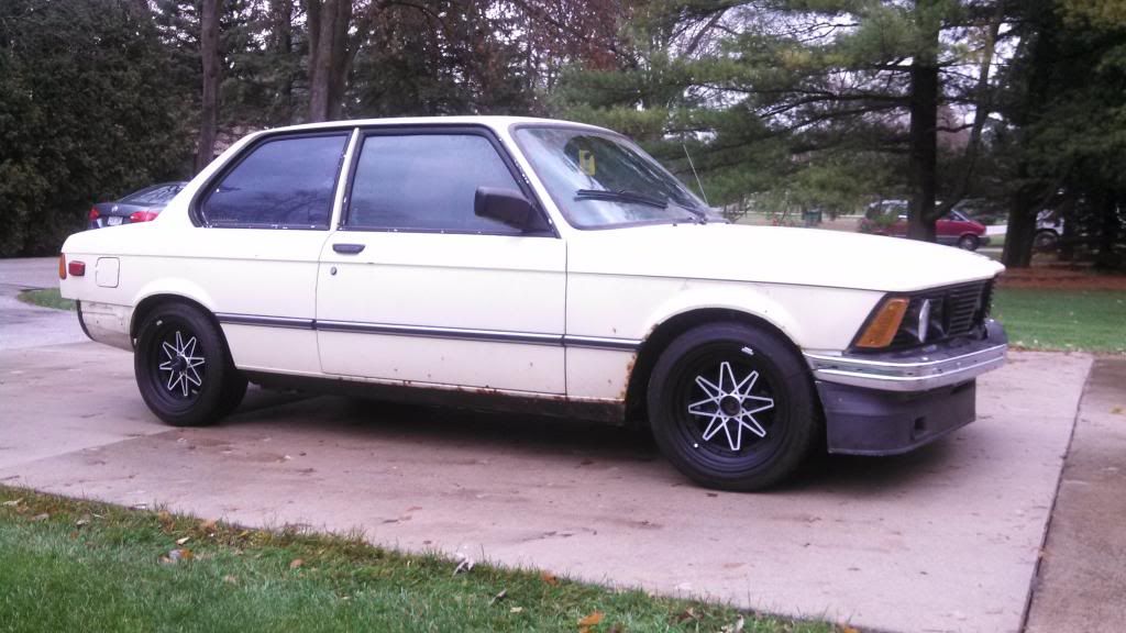
-
dat mono-wiper dooeeee
but in all seriousness Dave, awesome!!!
-
im updating your crap for you.
Last night was Megasquirt Party 2013 at my house.
I know it was a party because there were lights, music, and there was megasquirt.
Bassboy picked up an MS1 ECU and we did the processor upgrade to convert it to MS2.
Here is what an MS V2.2 PCB looks like (MS1 processor removed)
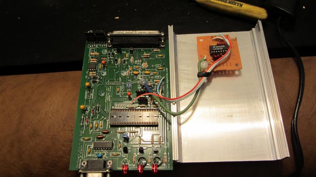
It was very simple, but just required thoroughly checking pins and wires to make sure we were soldering and connecting things to the right spot
This is the MS2 daughterboard which replaces the MS1 processor.
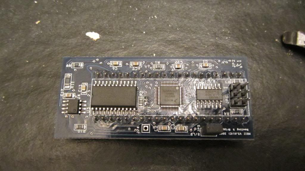
We connected the ECU to the computer, ran the bootloader software, then installed the latest version of the Megasquirt firmware on it and started piecing together the initial settings and tune file.
So far it appears that the upgrade was successful. The final test being when its up and running on the car.
-
I can't believe I haven't seen this. Just read the thread and I'm all in! The color combo is kickass.
Engine shots? Motor pics?

@DrLeadFoot
-
im updating your crap for you.
Last night was Megasquirt Party 2013 at my house.
I know it was a party because there were lights, music, and there was megasquirt.
Bassboy picked up an MS1 ECU and we did the processor upgrade to convert it to MS2.
Here is what an MS V2.2 PCB looks like (MS1 processor removed)
It was very simple, but just required thoroughly checking pins and wires to make sure we were soldering and connecting things to the right spot
This is the MS2 daughterboard which replaces the MS1 processor.
We connected the ECU to the computer, ran the bootloader software, then installed the latest version of the Megasquirt firmware on it and started piecing together the initial settings and tune file.
So far it appears that the upgrade was successful. The final test being when its up and running on the car.
^^ Yeah what he said!
I can't believe I haven't seen this. Just read the thread and I'm all in! The color combo is kickass.
Engine shots? Motor pics?
Thanks man! I can grab some shots, nothing much has changed right now engine wise until I start the megasquirt install tho.
-
how i imagine Dave and Brian at their MegaSquirt gatherings

-
Yep, and as soon as a few more of you guys discover the joys of megasquirting the parties will intensify
I wanna party.
Sent from my SCH-I535 using Tapatalk
@DrLeadFoot
-
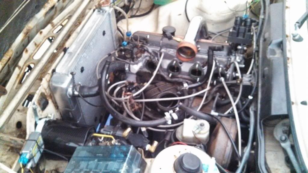
Well she is back under the knife. I am beginning the megasquirt efi install now that the edis setup is working perfectly. Took the intake manifold off the other day and worked on the m30 throttle body install and adapter I made to raise it up a tad for the charge piping to clear the valve cover.
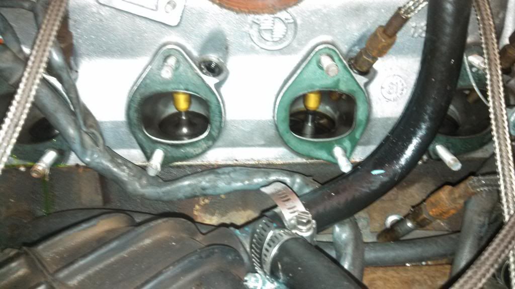
The goal is to drill holes in the manifold runners for the efi injectors to spray at the rear end of the valve. You can see where the CIS injector sits in the head and where it aims here.
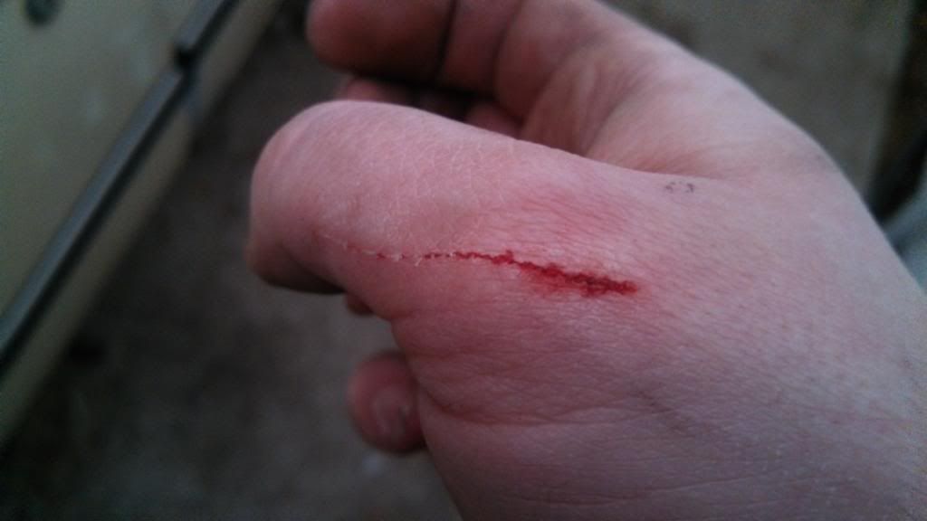
Scars, scars, and more scars. Taking that manifold off was a bitch!!
This also reminds me I never posted a finished picture of the throttle body adapter I made.
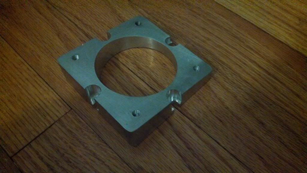
Old throttle body off, mounting holes for the adapter marked.
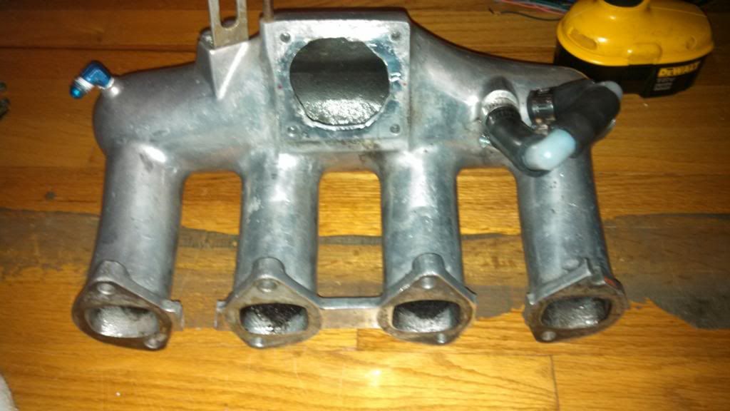
Holes were then drilled and tapped. M30 throttle body and adapter test fitted.
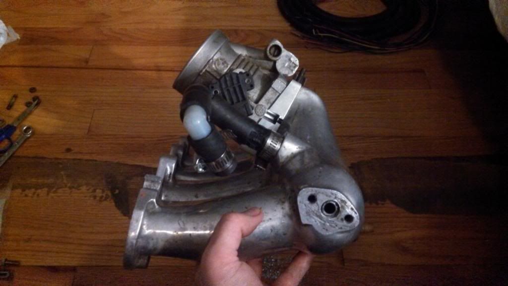
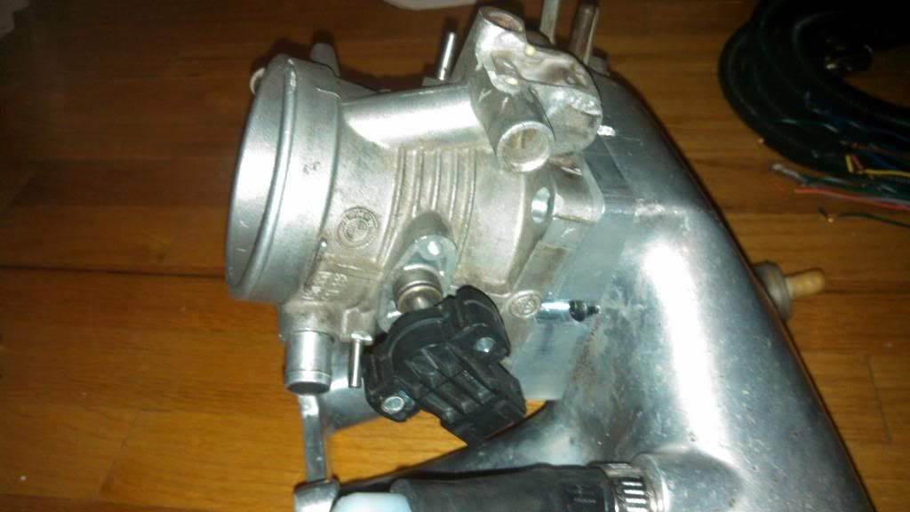
Next will be to create a jig somehow that will allow me to bolt it down to the manifold, and have guides for the drill bit to drill the holes for the injector bungs at the precise angle for each runner. If any of the injectors are a tiny bit off, it will cause a leak issue at the fuel rail which wouldn't be good. The jig will take lots of time and fabricating to make, but I think its the best way to get all the injectors lined up perfectly.
-
drill it by hand.
got a perfect drill master corded drill somewhere.
don't worry, I misplaced the chuck many moons ago.
-
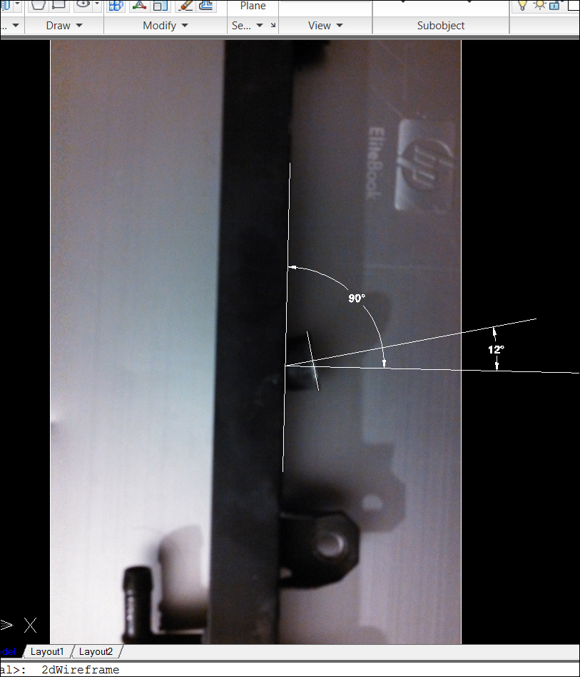
Started calculating the angles and drawing up the jig in autocad. First I found the injector angle on the 318i fuel rail. I calculated it with a protractor to be 13 degrees. I then took a picture of the rail and drew up the angles in CAD and got 12 degrees. Pretty darn close. I decided to go with 12 degrees.
From there I came up with a "simple" jig. The jig will be created from plywood. Two pieces connected at a 90 degree angle with bracing on the sides. The manifold will then be bolted to the vertical piece of plywood at the correct 12 degrees. This will allow me to place the entire assembly on the drill press and the holes will be the correct 12 degrees for the fuel rail. I used a generic manifold for the CAD model, so don't freak out too much.
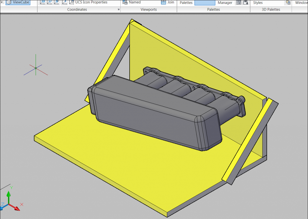
My thinking is this. First, I drill the holes to the fuel rail angle of 12 degrees. Then to get the correct angle for the injectors to fire fuel at the back of the valve as needed, I will then oval out the holes either with a boring bit or a dremel until the injector bung is sitting in correct position.
OR, my other thinking was I could make the jig so that the outer braces are longer and have slotted holes. That way the entire vertical piece could be tilted backwards to the correct angle for the fuel to flow at the back of valve. This way in one movement of the drill press the holes will be at BOTH of the correct angles simultaneously. This will obviously take more fancy work with the jig. I am still debating which route I should take. Don't want to mess up my one and only intake manifold.
-
#1 Nice idea on the jig. that is pretty much what I had in mind also.
#2 Use SolidWorks.
#3 My vote still stands for "oval out the holes either with a dremel" after drilling.
If you muff it up you can always just scrounge the internet for the next 10 years looking for another BAE intake manifold for sale. No big deal.






 M50) said:


Hello! It looks like you're interested in this conversation, but you don't have an account yet.
Getting fed up of having to scroll through the same posts each visit? When you register for an account, you'll always come back to exactly where you were before, and choose to be notified of new replies (either via email, or push notification). You'll also be able to save bookmarks and upvote posts to show your appreciation to other community members.
With your input, this post could be even better 💗
Register Login